
Methodology and Tools for Digital Twin Management—The FA3ST Approach
by
 , , and
Ljiljana Stojanovic
*, 
Thomas Usländer
 ,
,
Friedrich Volz
,
Christian Weißenbacher
*,
Jens Müller
,
Michael Jacoby
 and
and
Tino Bischoff
Fraunhofer IOSB, Fraunhofer Institute of Optronics, System Technologies and Image Exploitation, 76131 Karlsruhe, Germany
*
Authors to whom correspondence should be addressed.
IoT 2021, 2(4), 717-740; https://doi.org/10.3390/iot2040036
Submission received: 20 October 2021
/
Revised: 18 November 2021
/
Accepted: 24 November 2021
/
Published: 26 November 2021
(This article belongs to the Special Issue Industrial IoT as IT and OT Convergence: Challenges and Opportunities)
Abstract
:The concept of digital twins (DT) has already been discussed some decades ago. Digital representations of physical assets are key components in industrial applications as they are the basis for decision making. What is new is the conceptual approach to consider DT as well-defined software entities themselves that follow the whole lifecycle of their physical counterparts from the engineering, operation up to the discharge, and hence, have their own type description, identity, and lifecycle. This paper elaborates on this idea and argues the need for systematic DT engineering and management. After a conceptual description of DT, the paper proposes a DT lifecycle model and presents methodologies and tools for DT management, also in the context of Industrie 4.0 concepts, such as the asset administration shell (AAS), the international data spaces (IDS), and IEC standards (such as OPC UA and AML). As a tool example for the support of DT engineering and management, the Fraunhofer-advanced AAS tools for digital twins (FA3ST) are presented in more detail.
1. Motivation
Representations of real-world objects as digital models have been an innate topic of computer science. System modelers have always investigated how to represent features and properties of physical objects in an adequate and efficient way for a given task. However, in order to reduce complexity, and due to the limits of IT devices w.r.t. memory consumption, and processing capacity, the digital views were always focused and tailored. In automation technology, this means that the modelling of a machine in a production control system, in addition to identification data, just comprises those machine statuses and operational data which are relevant for an operator. Engineering data on type and geometry is typically not accessible from the production control system. Today, these distinct representations, usually stored and provided by different, mostly incompatible IT systems, hinder integrated modelling and simulation concepts of digital factory components as well as integrated industrial analytics.
The concept of a digital twin (DT) is about to change this limited approach, at least when understood according to its original idea described by Michael Grieves in his course on product lifecycle management [1]. Grieves argued that the basic concept of a DT is based on the “idea that a digital informational construct about a physical system could be created as an entity on its own. This digital information would be a “twin” of the information that was embedded within the physical system itself and be linked with that physical system through the entire lifecycle of the system”.
The DT term conveys the idea that there are many essential properties of digital representations that match those of their real-world counterparts. Moreover, the digital representation shall even be synchronized as much as possible with the status of the real-world object. Ideally, there is an exact image of all properties and functions of a physical component (e.g., a robot arm, a pressure sensor or a gauge), synchronized in (near) real-time during its whole lifetime. Consequently, an operation upon the DT shall instantly affect the physical component and vice versa. This vision of a complete and instantaneously synchronized image is, of course, not achievable in practice.
However, today’s embedded sensors, the sensor data processing close to the device (edge computing), the Industrial Internet of Things (IIoT) for networking of devices and ubiquitous data transmission (e.g., time-sensitive networking, 5G/6G wireless communication technology), as well as cost-efficient and uses scalable data storage reduce the latency in such a synchronization. Furthermore, complimentary to the processing close to the device, there is the option to store asset data in a cloud environment where it may be processed over the whole lifetime of an asset following the different business models of the engineering, operation and discharge phases. This means that, apart from the question of adequate modelling for given use cases, the management of digital twins (e.g., lifecycle management, versioning, interoperability issues) is getting more and more demanding (e.g., [2,3,4], see also Section 6). However, to our knowledge, a holistic engineering and management model for DT does not yet exist. This is the motivation of our work and the core topic of this paper.
The remainder of this paper is organized as follows. Section 2 clarifies the terms around the DT concept. While we propose a holistic approach for managing DTs in Section 3, Section 4 presents tools for DT management in the context of Industrie 4.0. Section 5 describes how the proposed methodology and tools are applied in a selected use case. After the related work in Section 6, the paper concludes with a conclusion in Section 7.
2. Digital Twin Concept
A comprehensive definition of terms around the DT concept is provided by the Digital Twin Consortium. From their glossary [5], the following terms are taken as a basis for our paper.
- A DT is a virtual representation of real-world entities and processes, synchronized at a specified frequency and fidelity. (Note that the set of real-world entities and processes is called a physical twin, i.e., the physical counterpart of the DT.)
- A DT use case is a use case in which DTs may be used to accomplish desired outcomes.
- A DT system is a system-of-systems that implements a DT.
- A DT platform is a set of integrated services, applications, and other DT subsystems that are designed to be used to implement.
Hence, when considering the engineering and, in general, the management of DTs, it is relevant to know which of the properties of real-world entities are required, how to map them to submodels, and how to realize a fitting synchronization frequency and fidelity. For a methodology on DT Engineering and Management, there is a need to consider an argumentation line from the:
- use cases to be realized and supported by the DT concept;
- the system requirements that are derived from these use cases in terms of their functional, informational, and non-functional properties;
- their mapping to the capabilities of the DT platform;
- the interface to the physical twin, i.e., to the real-world entities and processes.
Looking at the term “twin” in its essence, the term DT itself is misleading. Although biological twins exhibit many genetic matches and start from a common environment, they evolve and socialize largely autonomously and independently from each other, at least with increasing age. Conversely, the “socialization” and lifetime of a DT in a digital factory is basically independent of that of its real-world counterpart. However, due to its widespread use, we stick to using the term DT as well. In design and engineering departments, digital representations are created in virtual environments more and more close to reality. A robot arm may be simulated in its cooperation with other robot arms or humans, and optimized in its behavior before the physical robot arm is even produced and installed. In the virtual world, time may be wound back and forth as required. This enables the evaluation of past situations and the simulation of future situations by means of prognostic models. After the end of life of the physical objects, e.g., due to wear and tear or dismantling, the virtual representation may even be stored longer for documentation purposes. Despite the technological progress, even today, a DT only encompasses partial aspects of the real object. For example, one important aspect that should be addressed in the future is how to integrate historical data into a DT. Current standards and almost all implementations seem to agree that DTs only reflect the current state of an asset and do not provide any means to store or access historical data [6]. However, historical data are a relevant element, especially when it comes to applying, creating, or training models.
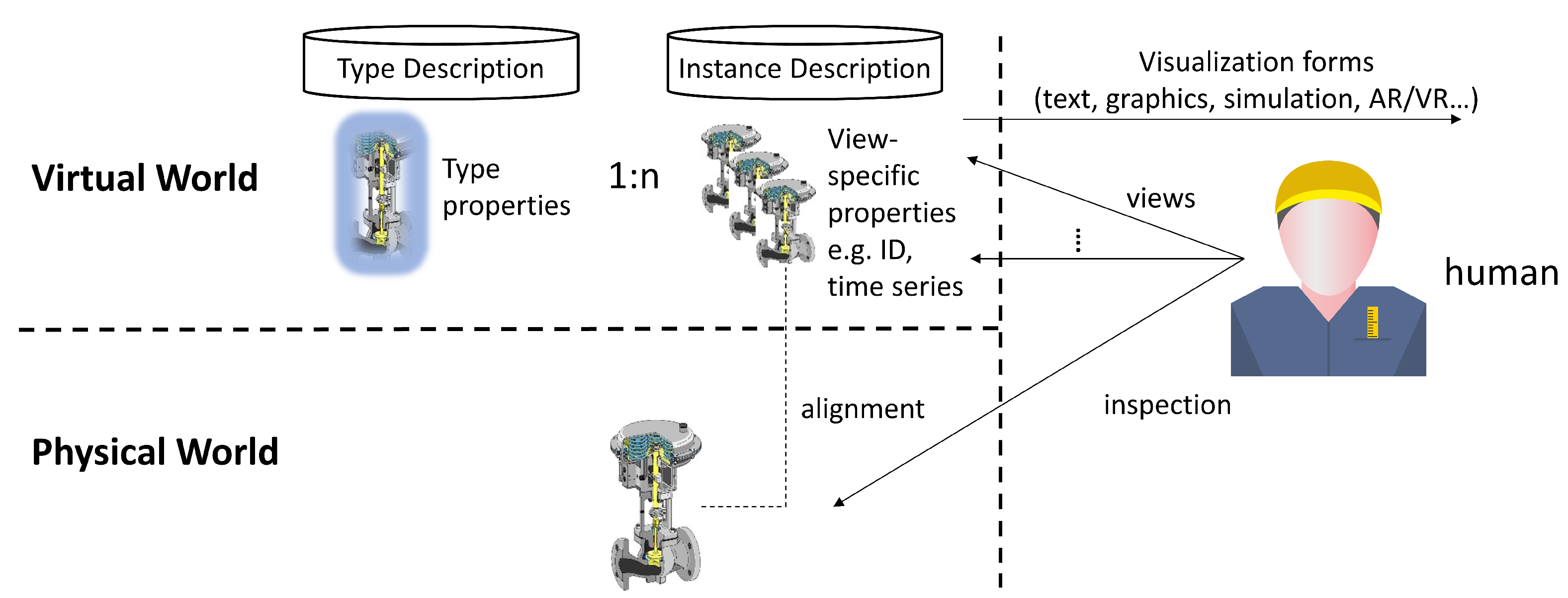
Figure 1 illustrates the conceptual view on DTs, taking a gauge as an example. In the virtual world, it has to be distinguished between a type description of a DT of a gauge, comprising generic properties of a gauge type, such as its geometry, diameter, closure, and fluid flow characteristics, and instance descriptions, representing a dedicated gauge with its ID, its location, its status, and its operational usage data. It may be assumed that, by giving an indefinite amount of effort and time, a nearly perfect double of the physical gauge may be modelled in the virtual world. In reality, only a subset of it is available and also necessary. These virtual representations shall be made accessible in a DT backend platform. Front-end services provide views upon these data and create a visual based on the demands of humans and their roles as well as industrial software applications.
To be applicable, for example, in a production environment, the software used to realize a DT should be capable of supporting the requirements arising in the specific domain. Furthermore, identifying and modelling the necessary aspects of a DT may be challenging, as well as to get the most out of the usage of the digital twin by sharing the data contained in it in a controlled manner. This is why we propose a concept on how to manage DTs along their lifecycle. By supporting the creators of DTs along the lifecycle, we simplify the creation and modelling of the DT and propose a well-defined process for reproducible results.
In Industrie 4.0, these metadata sets are logically contained in the so-called asset administration shell (AAS) [7] with well-defined application programming interfaces (APIs) to access the metadata elements [8]. The AAS distinguishes between submodels that are determined by application domains, industrial branches, and its standards and views, which are defined by the functional and informational shell of those properties that are required by the intended use cases. Consequently, the AAS provides a technological framework for the design and set-up of a system of interoperable DTs.
3. Our Approach for Digital Twin Management
In recent years, we have seen significant growth in the research and applications of DTs. Several methods and tools have been proposed to support DT development [2,3,4,9,10]. In this paper, we propose a holistic, systematic approach for the management of DTs, which is flexible enough to deal with assets of any types and scale. The proposed approach considers the following aspects.
- DT lifecycle: What needs to be done (in each lifetime phase)?
- DT stakeholders: Who can do that? This refers to both a DT user with requirements on the DT and a DT engineer.
- DT tool support: What would be the most appropriate means to automate activities or to help stakeholders perform them easily, efficiently, and effectively?
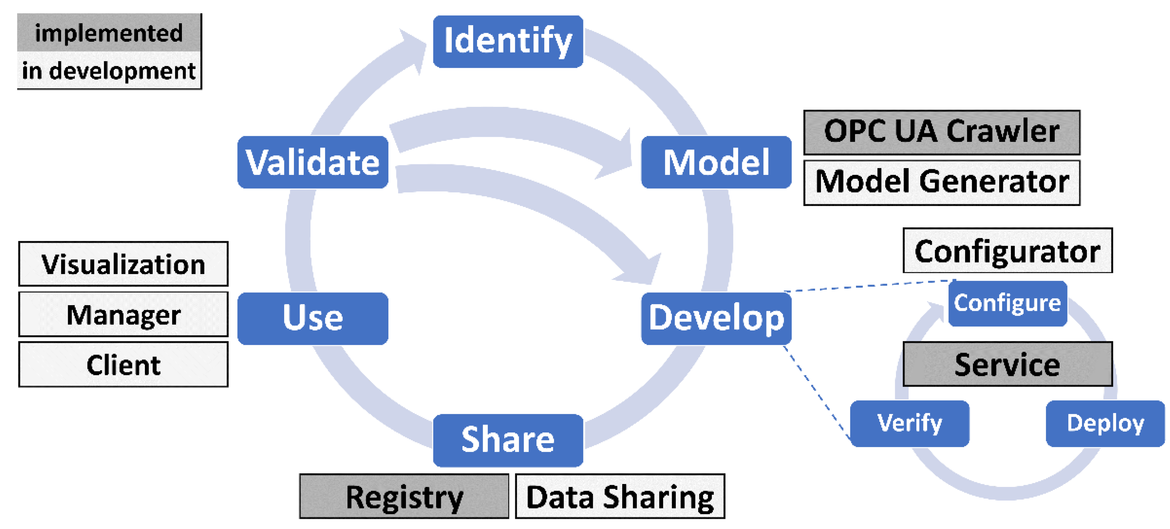
We define a DT lifecycle as a series of phases through which a DT passes during its lifetime, each of which significantly contribute to the final result with specific focus. As shown in Figure 2, the DT lifecycle refers to the process of identifying, modelling, creating, sharing, using, and refining a DT. The phases are organized in a cycle, as the DT could be dynamically refined over time. For the rest of the paper, we assume the following definition of a DT: A DT consists of (1) data of a physical system that represents its attributes; (2) models that describe the behavior of the physical system; and (3) a set of services that use the data and models. For more complex use cases, a DT may also include or reference other DTs.
Below we provide more details about each phase. Our goal is not only to provide a more methodological approach, but also to identify knowledge and skills, and recommend technologies and tools for managing DTs. Thus, we also discuss the expertise required to execute a phase and the potential tools that could help users accomplish the tasks.
Based on our experiences in developing DTs as well as by combining insights from knowledge management systems, (model-driven) software engineering, and existing approaches for DTs, we propose the following phases.
- Identify: A DT is a digital representation of an asset. Before creating a DT, it is mandatory to clarify why it is needed and what should be achieved.
- Model: To develop a DT, the data and behavior of the physical system must be modelled.
- Develop: The result of the development phase is a deployable software artefact. Based on the DT model, data must be collected, pre-processed, and stored, and a variety of models/services could be applied to it. The DT should not only be made available for human use, but „authorized” external systems and/or other DTs should also be able to access its data, run its models, and invoke its services. As the software counterpart of a real asset, the DT should, therefore, provide various APIs for connection and interaction.
- Share: The DT should be stored in a (DT) repository to be accessed, (re)used, and possibly customized.
- Use: The DT should be placed in context to be able to operate (e.g., the DT must have data connections to the physical system (and other entities) and a platform to run models). In this phase, the data are fed into the DT, the interaction is logged, and the feedback is collected.
- Validate: The DT should be kept up to date. This also covers evaluating its synchronization with the physical system (frequency and degree of fidelity). It should be reviewed continuously to ensure that it is relevant, valid, and correct for given use cases.
A well-defined approach to the entire lifecycle of a DT can help to reduce the individual effort required to create a DT while ensuring that the DT is of high quality. Furthermore, a DT management concept that considers DT sharing and continuous DT improvement prevents the reinvention of the wheel on the one hand and ensures the maintainability and, to a certain extent, the resilience of DT solutions on the other hand. Such an approach could be useful in identifying bottlenecks in DT data collection, processing, and delivery, and in highlighting which human skills or DT components need to be improved.
The key challenges of each phase, considering what should be done, by whom, and what tools might be used, are summarized below.
3.1. Digital Twin Identification
There are many possible drivers for creating DTs, such as strategic reasons, solving operational problems, innovating by introducing new services, or improving the services offered, etc. Before developing a DT, the domain of interest represented by the DT should be made clear, as well as the purpose and benefits of the DT. Information gathering, analysis, and consolidation should be performed to ensure full understanding and to be able to address challenges.
One means to scope the DT could be capability questions. They consider the stakeholders’ demand, as they include questions that the DT stakeholders want to get answered by using DTs. Thus, they could be helpful to define requirements for the DT. Additionally, they can be used during refinement to verify and validate the DT.
Typical examples include the following.
- For what asset is the DT to be created?
- Is there a need to decompose the asset into parts that require additional DTs? If so, the parts should be identified and the same approach should be applied to each part.
- Is it necessary to consider the asset in the context of a “larger” entity rather than in isolation? If yes, the entity should be identified and the approach should be applied to the identified entity rather than the asset.
- What would be the main purpose of the DT? To collect information centrally or to provide monitoring, diagnosing, predicting and prescribing capabilities?
The capability questions help determine the right level of granularity for the DTs and assist in understanding relationships between DTs if more than one DT is needed.
The more capability questions available, the easier it will be to develop a DT. The capability questions can be developed manually or automatically (e.g., from a repository). They should be reusable as they are independent of domains/assets, and they should be ordered to enable step-by-step gathering of requirements. The questions should be answered by the stakeholders responsible for the vision and innovation with the support of domain experts with their knowledge of an existing solution and the challenges to be considered.
3.2. Digital Twin Modelling
The capability questions specify what should be included in a DT and, thus, they can be considered as requirements for the content of the DT. The next phase is to capture the DT content. The result of the DT modelling phase is a declarative model of a DT.
Each DT model must conform to a DT meta model (such as the asset administration shell [7]), which specifies the core elements of a DT (such as the attributes, models, services, and other DTs) and their relationships and constraints. There are many languages to model DTs. An overview of the standards can be found in [11]. To achieve interoperability with other DTs and with external software systems, it is important to use a standard for modelling a DT. Only this way can the content of a DT be unambiguously understood.
In this phase, the core elements of a DT should be identified (such as the parameters of a machine), described with metadata (such as the data type, quality, constraints, etc.), related to each other and/or to external models and services and finally formalized in a form that can be understood by both human and DT systems. However, it is not mandatory for a DT to contain all core elements. It depends on the application domain.
There are many different ways to create a DT model:
- manually e.g., by filling in a template, by using a DT editor (in a way similar to using the AAS Explorer [12]), by answering more detailed capability questions, etc.;
- by instantiation, e.g., by creating a DT for a concrete asset based on a DT for a type of that asset (e.g., a DT of a concrete machine instance used by a factory operator can be created from a DT of a machine type for this machine provided by a machine supplier);
- by combining/reusing existing DTs to create a DT for system of systems (e.g., a DT for a machine may contain DTs of all its components, or a DT for a supply chain may consist of DTs of all partners in a supply chain);
- by exporting parts of a DT model from relevant software systems (e.g., planning, computer-aided engineering (CAE), manufacturing execution system (MES), enterprise resource planning (ERP), etc.) and hardware systems (e.g., OPC UA [13] server/client of a programmable logic controller (PLC));
- by analyzing existing documentation, e.g., by extracting information from Excel files describing a list of products.
Conformance checking should always be applied to ensure that the created DT model conforms to the DT metamodel. This assumes that there is a formal definition of the metamodel.
Joint work by domain experts and developers is required to develop a DT model. The domain experts have the know-how, e.g., to decide the most important attributes, what the most relevant models to be considered, etc. While the domain experts know which asset parameters are important, the developers have to check the availability of these data in existing hardware and software systems. The more the creation of a DT model is automated, the more intelligent tools are needed, and the higher the involvement of software developers.
3.3. Digital Twin Development
The result of the DT modelling phase is a concept or a formalized model of a DT. The goal of the DT development phase is to create a software artefact for the DT based on this model. This software artefact should be connected to the physical artefact (e.g., a machine); should include standard services (e.g., visualization) and domain-specific services (e.g., for predictive maintenance); and should be integrated with external hardware and software systems to ensure data collection, asset control, and DT usage. During the DT development phase, the DT software artefact is deployed and the APIs should be made available for applications, systems (e.g., MES, ERP, etc.), devices, humans, etc., to access the DT entities and use services provided by the DT and its physical twin.
The DT can be developed manually. However, to reduce error, improve productivity, and enable automatic updates, model-driven software engineering approaches should be applied to leverage the DT model that has already been created. Given the DT API specification, DT code generation could be a useful approach for creating and maintaining DTs. The role of a DT generator is to generate, e.g., Java classes based on the DT model. This ensures that the DT is always consistent with its model and it helps to update it when the model is changed. There are several approaches for DT generation based on a domain-specific language (e.g., [14]). However, to ensure interoperability, it would be better to use standards. In [15], the authors confirmed that the asset administration shell can support DTs not only for manufacturing but also in use cases beyond.
It is important to note that not only should the model of a DT and its interfaces conform to standards, but the internal structure of the generated software artefact should too. This will ensure expandability with additional services and will prevent vendor lock-in. For example, ISO 23247 [16] defines a framework to support the creation of DTs for manufacturing. The framework can be applied to different types of assets, including personnel, equipment, materials, processes, products, documents, facilities, etc., and to both discrete and continuous manufacturing of parts, assemblies, and material. In addition, various technical aspects, which must be taken into account when realizing a DT, are defined in the IIC whitepaper as “Digital Twins for Industrial Applications” [17].
Unfortunately, although many steps of DT development can be automated, the DT software artefact cannot be generated based on the DT model alone. Several aspects related to both functional and non-functional requirements need to be configured. Such a configuration also ensures that one has control over what is generated and how. Thus, to reduce or even to eliminate involvement of the software engineers to adapt the generated code where necessary, the development of DTs should be configurable.
In order to be able to define the DT features, the following aspects should be considered:
- bi-directional asset connection for attributes, models and subscriptions (e.g., via standardized communication protocols, including OPC UA or MQTT);
- data translation to the internal DT model including syntax adaptation and semantic awareness;
- interfaces to be provided to the external users (e.g., on which port the REST API will be listening);
- persistence for real time data (e.g., in memory storage, or in multiple, different internal/external databases);
- storage of and access to historical data;
- caching strategy for static or slowly changing data;
- integration of model execution environments to execute the models (e.g., physical models, data-driven, etc.) (we note here that a model represents a logic processing step that needs to be executed);
- security support, such as authentication, authorization, and even usage control.
The generated DT has to be executable. Thus, the DT generation phase creates value, not only by generating the software representation of a DT, but also by compiling the code and allowing it to be deployed flexibly. With the emergence of container technologies, such as Docker, it becomes easier to encapsulate a DT and its dependencies into reusable images and make it available to others by deploying it e.g., in the cloud.
The DT should be verified before use. It is not only a matter of verifying whether the right DT is produced with the required degree of fidelity. Verification answers the question as to whether the DT meets non-functional requirements, such as scalability, performance, efficiency, deployability, etc. Based on the verification results, it may be necessary to restart the DT generation by changing the configuration to satisfy the non-functional requirements.
Manual DT development and, to some extent, DT generation require software expertise. Therefore, it must be performed by the software engineers. The involvement of domain experts is only necessary for the setup of the configuration to clarify priorities and expectations.
As for tool support, DT code generation and deployment could be fully automated. For verification, the generated DT needs to be tested for many aspects, as specified in the configuration. Several generic tests could be provided for each non-functional requirement, but there is always a need for DT-specific tests to be implemented.
3.4. Digital Twin Sharing
While the DT development phase provides an accessible and interoperable executable DT, the DT sharing phase makes the DT discoverable and reusable. These two phases ensure the FAIR principles [18] for DTs.
When a DT is shared, there is less risk of losing valuable experience that others can benefit from. In fact, DT sharing is an optional activity through which information about a DT or a DT itself is shared within or between organizations with the goal of creating and sustaining competitive advantage. For example, sharing DTs within an organization can prevent reinvention and, thus, promote more efficient and effective reuse. A typical example is that a DT created for the engineering phase of a production system can be extended for the operational phase of the production system by, for example, including the data-driven models in addition to the simulation models.
There are many approaches that can be used for DT sharing, such as file sharing by exchanging declarative DT models, traditional centralized approaches, or even distributed or decentralized peer-to-peer approaches (e.g., using blockchain technologies) [19]. However, to make a DT not only visible but also accessible, there is a need to store the metadata about DTs (and possibly the DTs themselves) and to control access to them. It is up to the owners of a DT to decide if the DT should be shared and to clarify its accessibility and sovereignty level [20].
The most effective DT sharing approach should be able to retain relevant DTs while ranking lower or even forgetting DTs that are no longer important (e.g., based on their use). In the case that the DT metadata are held and maintained centrally, the tool support should include a DT registry that should offer functionalities to register DTs, find them, rank them according to their importance for the user’s information needs, notify the “interested” parties, and to flexibly interact with them by referring to or replicating them. Additionally, the registry can be also used for storing “abstract” DTs (e.g., for a machine type) that could be filled in with concrete values when creating a DT of a concrete machine.
3.5. Digital Twin Usage
The DT usage phase focuses on using a DT in an efficient way to provide a competitive advantage for the business. As it is the application of a DT to business decisions or opportunities, the DT should be used on demand, which, for many use cases, means it is used continuously. It should also continuously generate feedback to be considered for DT improvement.
DT users can be people, devices, or software systems that utilize a DT. While people are mainly interested in services provided by a DT (e.g., visualization), for the hardware and software systems DT functionalities should be available via an API. Both reactive and proactive modes of use are required for all types of users, and appropriate interface shall be provided.
Tool support should include a DT manager who monitors all DTs used in a company. Such a system should indicate how a DT is used, and should report any difficulties. It should allow interaction with a DT using the DT APIs and services and enable the DT to be started and stopped. Additionally, it should inform users when the DT model is changed. Finally, it should log all interactions with the DT. The logging of a DT usage should not only include the monitoring results, but also the identification of errors and their resolution.
No special knowledge is required to use a DT. However, to understand the results of DT services, the domain-specific knowledge is required. For example, a DT may include highly specialized or advanced models of physical processes that require expert knowledge to configure. Regarding the use of a DT by a hardware/software system, the software engineers should be involved at the beginning to solve integration problems.
3.6. Digital Twin Validation
It is important that companies measure how DTs contribute to their business success. As for any software system, it is a difficult but important task to validate the development and use of a DT. The DT should be continuously validated by checking whether and how the generated DT captures the needs collected in the DT identification phase.
Due to changes in the data, the operating environment, the technical capacity, business dynamics, etc., the DT should be able to incrementally improve its data, models, and services. For example, the DT services can be continuously expanded as new business requirements arise, or the DT model should be updated after new sensors have been installed. The changes can be triggered or can be detected. For example, a machine learning model can be retrained on demand or incrementally improved. The DT can be improved by modifying its model and rebuilding it, or even by updating the running DT (without stopping it) in order to prevent data loss.
The result of the validation phase includes three opposing actions, either (1) a completely new DT should be developed; (2) a slightly changed DT model should be created; or (3) an existing DT should be updated, starting from the DT development phase. Whereas the whole process has to be restarted in the first case, in the second case, the process restarts from the DT modelling phase. For the third use case, it is enough to start from redeveloping a DT, e.g., by updating its models. It could be also feasible that several DTs are continually in operation and their results are compared or combined.
4. FA3ST Tools for Digital Twins
In the previous section, a DT lifecycle was defined. For each phase, the requirements for tools to automate activities or facilitate their implementation by stakeholders were discussed. In this section, we present tools that provide support for the different phases of the DT lifecycle. Using tools that realize the different phases can increase the efficiency when applying DTs by providing a higher level of automation.
On a conceptual level, the proposed tools can be applied to DTs developed according to different standards. However, implementation is carried out based on the AAS specification [7,8], which is still evolving and does not cover all relevant aspects in full detail yet, for example data storage and security. We developed the Fraunhofer Advanced AAS Tools for Digital Twins (FA3ST) software ecosystem that allows easy and fast creation and management of AAS-compliant DTs.
Figure 3 shows the assignments of the FA3ST tools to the DT lifecycle. Different colors are used to indicate the status of development as of November 2021.
4.1. FA3ST Model Generator
The companies which will use the AAS to digitalize their assets already have data present in various software tools, such as ERP, MES, or CAD systems. These data can range from:
- meta data: general information about the asset (e.g., manufacturer or machine type);
- static data: additional data artifacts describing the assets generated during the engineering process (e.g., the bill of material or technical description);
- dynamic data: (live-)data arising during the production time with a high frequency of changes (e.g., sensor values or calculated values, including prices).
In addition to the heterogeneous kind of data, different aspects represented by an AAS can originate from different systems. Therefore, the modelling of such an AAS can be complex and, depending on the asset, can require lots of manual effort. This would result in the need of dedicated personnel with in-depth understanding of AAS modelling. As this would be redundant work and hinder the cost-effective application of the AAS, there is a need to create the AAS from the structure and data within the systems in an easy and robust way. The necessity to automate the creation of AAS is already recognized. For example, [21] describes the workflow of how product lifecycle management (PLM) software can create AAS templates, which are instantiated later in a manufacturing environment.
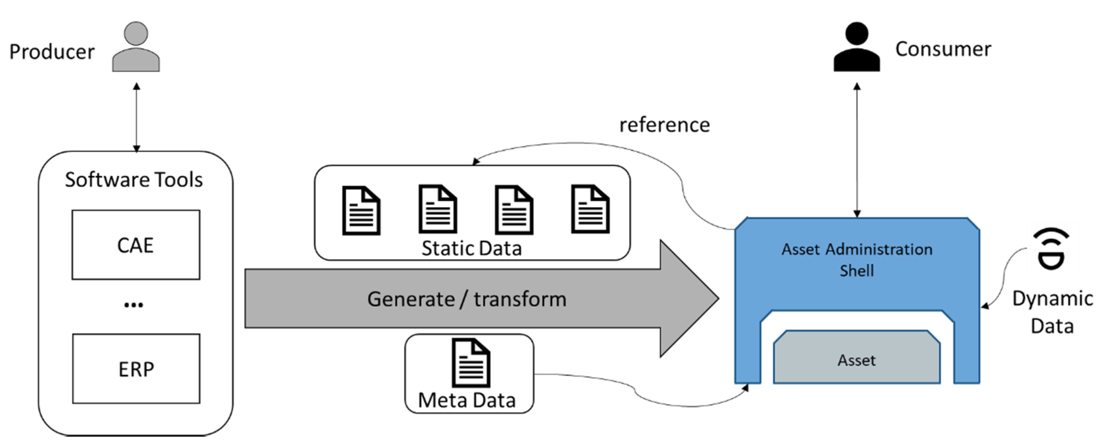
Figure 4 shows the transformation process of existing data into an AAS based DT. The DT should be capable of holding all three types of the assets data. Thus, it references the static data, takes the meta data of the asset as own meta data, and holds the dynamic data. This requires a suitable DT model which needs to be adjusted for the asset type to be able to capture all the data.
Currently, the AAS specification is still evolving, which makes it challenging to cost-effectively implement export functionality in existing software tools. Additionally, there are already established data exchange formats which are used to export data in the engineering tools. There is a wide range of data exchange formats, ranging from general formats, such as comma-separated values (CSV), to specialized ones, such as automation markup language (AML) [22]. During the lifecycle of an asset, several tools are used to define information for the asset, such as engineering data or economic data. The entire data created along the lifecycle belong to one asset and should be captured by its AAS. Thus, heterogeneous data models from different sources need to be converted and combined into a single AAS. Although the asset data are continuously updated in the various software tools, the associated AAS needs to be notified about the changes so that the AAS always represents an up-to-date version of the asset. Therefore, there is a need for a connection between the data sources and the AAS.
Part 1 of the AAS specification [7] defines several protocols to serialize AASs in different formats, such as JSON, XML, or AML. The latter is an open, vendor neutral, XML-based, and free data exchange format for industrial automation and control systems, defined in the IEC 62714 series [23,24]. Additionally, AML is integrated as a data exchange format in several CAE tools, such as EPlan (an electrical planning tool) [25], TIA Portal (a Siemens automation tool) [25], or RF::Suite from EKS InTec (a virtual commissioning tool) [26]. This already existing tool support allows two potential solutions to make the data available within the concepts of the AAS. The first option is to map the tools export feature according to the AAS meta-model. Relying on the AAS meta-model means keeping each of the tools up to date with the AAS specification, which is still currently evolving. This approach results in higher efforts on the tool providers side, but bears the benefit that users do not need to have deep knowledge of the AAS specification. The second option is to implement a stand-alone tool capable to read widely used input formats, such as AML, and to create custom mappings by users. Thus, the existing export functionalities of a variety of CAE, ERP, and other tools can be used as input for the mapping tool without the need for any special customization.
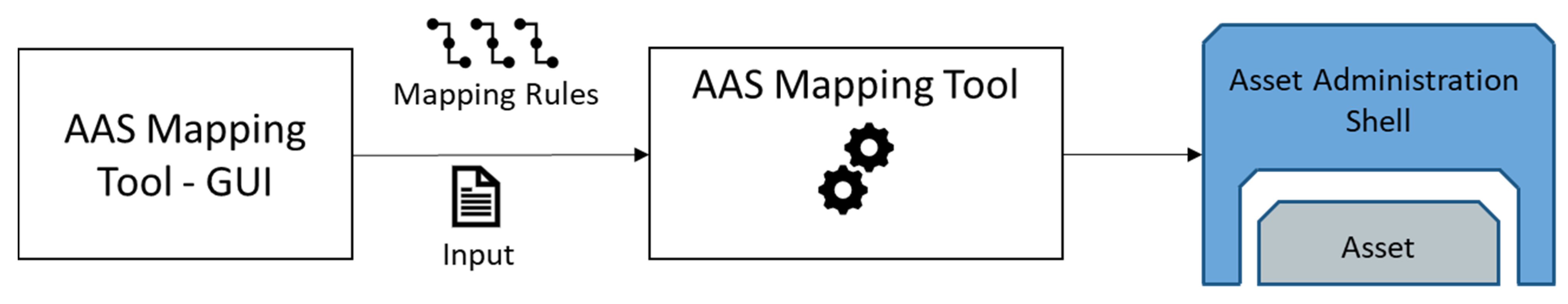
We are currently developing a mapping tool to manually create mapping rules from various formats into an AAS model, as shown in Figure 5. The tool will help to import an asset description in a specific format, such as AML or OPC UA Nodeset, and transform it depending on the previously defined mapping rules into an AAS model. Since the mapping rules do not depend on specific values but on the data structure of the input asset, the created mapping rules can be reused to generate other AAS from assets with the same data structure but with different values. This can speed up and simplify the creation of AAS models of existing assets.
4.2. FA3ST OPC UA Crawler
An AAS can be modelled in an OPC UA server using the OPC UA Companion Specification for AAS (I4AAS) [27]. In case additional functionality is required, e.g., with access to the AAS via additional endpoints, such as HTTP, it is necessary to create a full-fledged AAS based on the already existing AAS-compliant OPC UA Server.
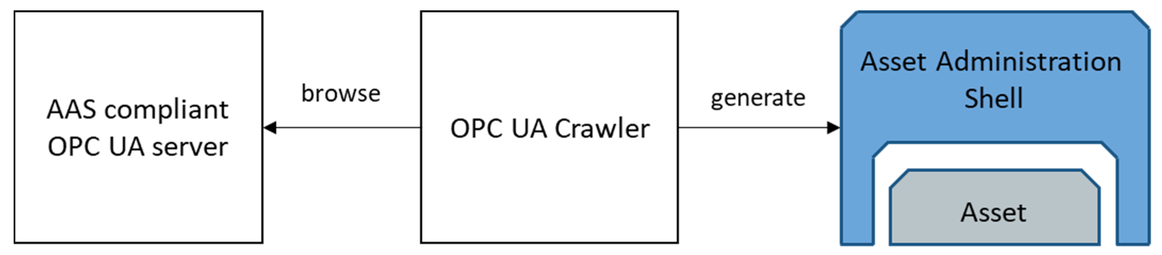
Currently, there is no such tool available. We created a tool, called the OPC UA Crawler, depicted in Figure 6, to create an AAS from the address space of a running OPC UA server. As we developed the tool in a very early phase, we faced the challenge that I4AAS was not yet released and no AAS compliant OPC UA servers were available. It is a Java-based library which contains an OPC UA client. The OPC UA client browses the OPC UA server and extracts the necessary information based on I4AAS from the address space and creates the AAS for FA3ST. Besides the AAS model, the OPC UA Crawler also creates an asset connection that can map all incoming HTTP requests to the OPC UA server by enabling the deployed AAS to act as proxy.
4.3. FA3ST Service
An essential step when working with DTs is to develop an executable software artefact providing access to the DT for external systems via standardized APIs. Typically, this is carried out using an existing software library tailored to that purpose. Development of a DT comprises the steps of configuration, deployment, and verification. As shown in Section 3.3, configuration of a DT comprises many aspects, such as supporting different serialization formats as well as communication protocols for the API and for asset connections. A DT software library, therefore, should abstract from concrete implementations for these aspects and provide suitable interfaces and mechanisms to easily adapt and extend the framework, e.g., by creating a custom asset connection for a legacy machine using a proprietary network protocol.
To address these challenges, we developed the FA3ST service component which enables the creation of executable DTs according to the AAS specifications [7,8]. It is designed to be easily configurable and extendible.
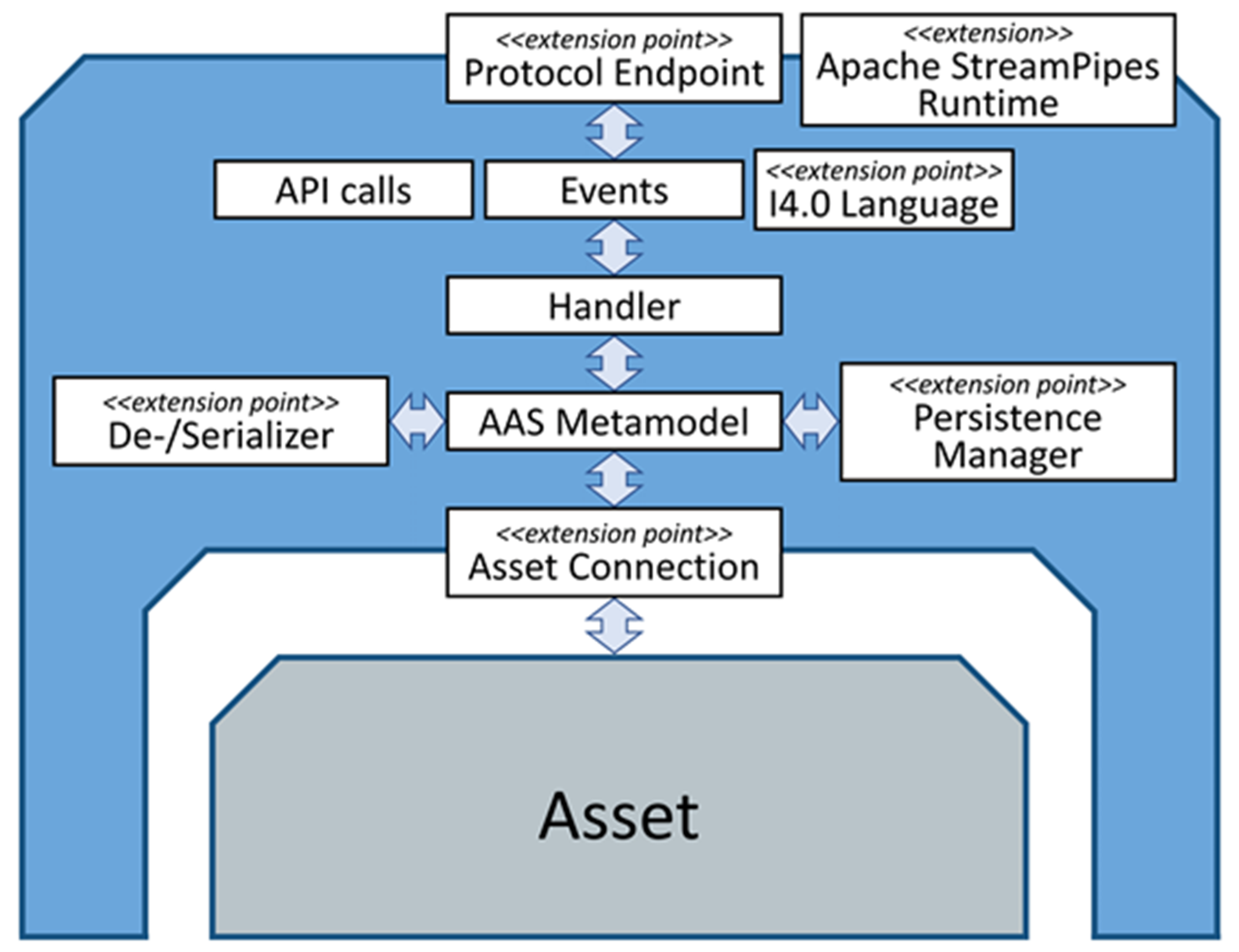
Figure 7 shows a high-level schematic diagram of the components of the FA3ST service. Elements with <<extension point>> represent Java interfaces which allows for easy extension and customization. The FA3ST service also includes some predefined implementation for these interfaces, e.g., a HTTP-based and an OPC UA-based protocol endpoint, JSON de-/serializer, file and database-backed persistence manager, as well as MQTT and OPC UA-based asset connections. It also provides an easy-to-use fluent API to create DTs from code, as shown in Listing 1. A FA3ST service can be deployed either as a Java JAR file or Docker container.
Listing 1. Code example showing how to create an executable DT using the FA3ST service
private static final String PATH ="/machine";
public static void main(String[] args)throws IOException,
URISyntaxException {
AssetAdministrationShellEnvironment
environment =
new
JsonFileReader().readFile("model.json");
AasService service = AasService.builder()
.environment(environment)
.dataAccess(new InMemoryDataAccess(environment))
.endpoint(HttpEndpoint.builder()
.port(8084)
.mapping(ISubmodellHttp.withPath(PATH))
.mapping(IAssetAdministrationShellHttp.withPath(PATH))
.build())
.build();
AasServiceManager.Instance.setAasService(service);
service.start();
}
As the current status of the specifications covers security rather on surface-level than providing detailed concepts, the FA3ST service does currently not implement any means to secure data or restrict user access. To not expose sensible data to the outside world, we strongly recommend to use it in combination with other security approaches, e.g., using a reverse proxy for the HTTP endpoint or our integration with the international data spaces (IDS), as described in Section 4.6.
Besides the FA3ST service, there are other open-source implementations that help to create executable DTs. The most prominent of them probably is the Eclipse BaSyx project [28] which originated from the BaSys 4.0 research project funded by the German Federal Ministry of Education and Research (BMBF). BaSyx provides support for Java, C#, and C++, and is rather feature-complete (i.e., it implements most or even all features of the AAS specifications). Compared to BaSyx, our implementation provides multiple unique features, such as the ubiquitous extendibility, and integration with Apache StreamPipes [29] (a toolbox for Industrial IoT with focus on stream processing) as well as with the IDS (see Section 4.6).
The AASXServer [30] is a C#-based implementation by the Industrial Digital Twin Association (IDTA) [31]. Both the FA3ST service and AASXServer offer an HTTP as well as an OPC UA-based service endpoint; however, in the AASXServer, they are not synchronized, meaning that changes to the DT via one type of endpoint are not reflected in the other. The AASXServer provides some functionality that is beyond the specification and not implemented by FA3ST Service, such as HTTPS/SSL, an MQTT endpoint, and a graphical user interface. Connecting the DT to existing assets is, however, limited to OPC UA.
NOVAAS [32,33] is a Node-RED-based implementation of the AAS specification by the research institute UNINOVA in Portugal. It has a strong focus on JSON, HTTP, MQTT, and usability, e.g., it provides a user management and a dashboard to visualize live data, but does not address essential parts of the specification, such as different data formats or OPC UA. In contrast to the FA3ST service, NOVAAS is realized using only Node-RED rather than being implemented as a classical code library which might be harder to integrate with other systems.
4.4. FA3ST Configurator
The FA3ST service provides the means to create DTs on code-level. However, not everyone wanting to create a DT in a software developer can manage the configuration. To make creation of DTs even more easy, we envision a DT configurator tool providing a GUI-based editor to configure all things relevant for the creation of a DT. Although FA3ST service provides many interfaces that may be realized by third-party implementations and, therefore, cannot be known to the configurator at design-time, the configurator should be able to provide a meaningful GUI to configure them. This poses a technical challenge but should be possible to overcome.
The configurator is currently in development. Since FA3ST is based on Java, the technical challenge can be solved with the Java reflection feature. With Java Reflection, classes of first- and third-party implementations can be inspected at runtime, and an appropriate GUI to select the configuration can be generated. However, additional abstraction is required to allow configuration without developer expertise. Currently, the design of the GUI is in evaluation to simplify the DT configuration. There is a clear clash between simplicity and the possibility to configure any class implementation. Too much abstraction will limit developers in the DT configuration, but allowing any class configuration requires the user to have knowledge of the implemented class.
4.5. FA3ST Registry
With several AASs distributed in a plant or another environment, there is more emphasis on the need for a system where AASs can be discovered. The more AASs are present in a system, the more difficult it will be to keep track of them. Thus, it would be necessary to have a kind of address book to search for specific AAS instances. This address book is called AAS Registry.
The interfaces defining the API to access the registry are described in Part 2 of the AAS specification [8]. They describe the communication between a client and a registry. The API should, on the one hand, be as easy to use as possible, and, on the other hand, it should be powerful enough to search for AASs with certain characteristics. Currently, the specification defines these interfaces only in a protocol-agnostic way, and there is no official mapping to concrete protocols, such as HTTP or OPC UA. With the FA3ST registry, we provide a preliminary and unofficial mapping of the protocol-agnostic registry API to HTTP using the REST principles which are easy to use and well known.
The basis for the registry content is the so-called “descriptor”, which can be seen as a light version of a concrete AAS. A descriptor has a standardized format which describes the endpoints of the AAS and the associated submodels. The registry API provides several methods to manage the registration. The AAS needs to be registered at the registry using its descriptor. If the information changes, it is also possible to update the information in the registry. Additionally, there is also a method to unregister from the registry, e.g., if the AAS is about to shut down. The registry also offers possibilities to query for registered components.
The FA3ST registry is, as all components of FA3ST, implemented using Java. Similar to the service, the registry supports the provision of different persistence implementations, e.g., in-memory or SQL database.
Another approach is the BaSyx registry [34]. It offers a similar API with some differences in the descriptor. This is because of the previously mentioned problem that the current version of the AAS specification only provides a protocol-agnostic API description, though there are no details on how to actually map this to any existing network protocol.
For some use cases, it would be beneficial to combine the AAS with the IDS. Since the IDS has a similar concept to the registry, called the IDS metadata broker, we developed a version of our registry which interacts with an IDS broker to better combine the two worlds.
4.6. FA3ST-Secure Data Sharing
Key issues in data sharing are trust, data leaks, and data misuse. This is the main concern of the security chapter in the AAS specification which specifies access control [7]. However, access control alone does not solve data sovereignty issues after data are shared [35]. Even when data are encrypted and users require the necessary authentication, data misuse, in the form of illicit sharing or usage for other non-agreed reasons, can take place. Data sovereignty describes the ability of data owners to specify the allowed usage of their data [36]. By strict compliance to the rules of the data owners in all processing systems, illicit sharing can be prohibited.
To realize data sovereignty, usage control frameworks are implemented in processing systems. Usage control is an extension of access control with additional obligations to the data users set by the owner [36]. While the AAS specification does not yet include usage control, the extension is currently a joint effort by Plattform Industrie 4.0 (PI4.0) and the International Data Spaces Association (IDSA) [37].
Implementations of the AAS, therefore, have to implement security measures, such as access control and authentication. In the future, with an extension to the present access control in the security chapter of the AAS specification [7], they might include usage control frameworks to allow data owners to include usage rules in the AAS. However, the security chapter is only concerned with additions to the metamodel to specify such usage rules and does not dictate on how to implement the security measures. The security specification is also in an early stage and is not trialed in the field. We can also see a different focus of the AAS security specification. While the IDS is mostly concerned with data sharing between companies and unknown partners, the AAS security focuses on attribute-based access control where persons from the same organizations might have different access rights and different ways that they authenticate.
A way to realize data-sovereign AASs right now is the usage of the IDS network [35]. By using the solution of the IDSA, the AAS can be integrated into the IDS architecture as an IDS app. Access and usage control, as well as all security aspects, such as authentication, certificates, and identity management, are then handled by the IDS connector, as compared to the AAS. However, IDS connectors communicate over the IDS API, requiring users to deploy an IDS connector for all communication. Data users without IDS knowledge would then be cut off from interacting with the AAS protected by IDS. This will limit users without IDS infrastructure by blocking their access to usage-protected data.
Additionally, if data owners require the AAS to implement usage rules, the AAS has to be part of the IDS connector. In the related work, “Shared Digital Twins” [38], based on the RIOTANA® demonstrator, a proprietary DT was put inside the IDS core container while an IDS data app translated the data according to the AAS REST API.
We recommend and implement another scenario where the DT is an independent service (not part of the IDS connector) and where critical data processing tasks are completed by IDS apps inside the IDS connector. The FA3ST service currently does not realize the AAS authentication or access control and leaves this to the IDS network. We are also implementing an IDS app that is specifically tailored towards easy connection of any AAS with the IDS. In the future, we will also realize the security aspects described in the AAS security chapter, but we remain positive that data-sovereign data sharing with usage control between companies is currently only possible in the IDS network. The joint working group between PI4.0 and IDSA is currently looking into combining both security specifications, but solving issues, such as identity management, will take more time [37].
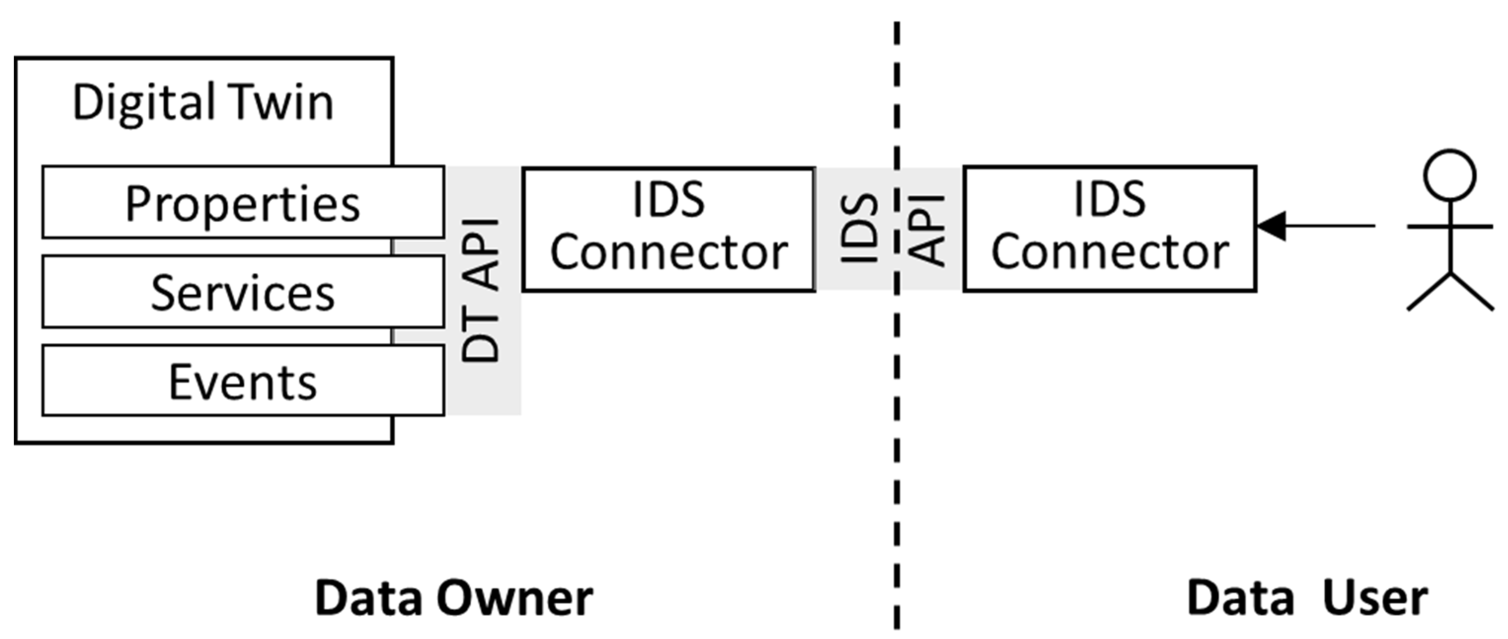
Figure 8 shows the interaction between data user and data owner, when the FA3ST AAS service is an independent instance in IDS interaction.
In this case, the AAS is an external IDS resource, and critical data are handled by IDS data apps. FA3ST was used and integrated with the IDS dataspace connector (DSC) [39] by configuring the connector instance. The DSC is an IDS-compliant reference implementation offering an IDS-ready certification [39].
AAS implementations providing usage control capabilities would also need some form of certification to make sure the usage rules are applied correctly. If this is not completed, data owners will be at the mercy of the data users not respecting the specified usage rules [40]. This, however, is also true for implementations with classic access control, since the data owner would not want unauthorized access by any errors (intentional or not) in the implementation and certification by audit will help reduce critical errors. Here, we see that the AAS security specification needs more research on the certification part to make sure that all AAS implementations confirm to the specified security aspects.
In summary, FA3ST is currently leaning on the IDS network to realize fine-granular usage control for the AAS. The implementation of data-sovereign AAS is a complex endeavor which will also change once the AAS specification extends the metamodel to address data sovereignty aspects.
The implementations have to be thoroughly designed with security and usage control in mind to reduce data misuse. Lastly, the certification of all software components used by data owners and data users is a vital part to create more trust between unknown partners and prevent data leaks.
4.7. FA3ST Visualization
During the usage phase in its lifecycle, a DT can be used to access information and data about the asset represented by the twin. To be beneficial for users, these data need to be accessible in a readable and interpretable way. Furthermore, as stated in Section 3.5, special knowledge or tools should not be required to access the data. Depending on the use case, interpretability can be achieved by using graphical elements to represent data. We currently develop the FA3ST visualization to make data easily accessible for users during the usage phase of a DT. To support different use cases or several users with different interests, several graphical elements can be grouped into separate dashboards. This allows for different views on data sources through the same tool.
By addressing the use case of visualizing data from AAS-compliant DTs, one faces the challenge of supporting the different protocols used by the AAS. Furthermore, tools that offer visualization should be capable of having connections with multiple AASs on different host systems, for example, to display data from various edge devices. This capability reduces the amount of running instances of the visualization tool and, thus, reduces required computing power and memory. The same applies to support of multiple dashboards, as different users have different expectations on what a dashboard should show.
The FA3ST visualization will become part of FA3ST and is a web visualization with a containerized front- and back-end for the AAS. By relying on web technologies, users can connect by using their standard web browsers. Additionally, the web-based approach allow one single instance of the visualization running, while being available on all devices within the same network. The FA3ST visualization allows users to create dashboards with configurable visualization elements, such as gauges, line charts, and tables. A subset of the visualization elements is depicted in Figure 9, showing data from the demo setup described in Section 5. Data coming from different assets (data sources) can be displayed within a single dashboard. Currently, FA3ST visualization helps to connect to data sources by using the protocol interfaces REST and OPC UA. To adjust the load on the data source, the OPC UA interface is subscription-based, while the REST interface helps to configure the update intervals freely.
4.8. FA3ST Client
All communication of external systems with a DT happens via its exposed standardized APIs. For a software system to communicate with a DT, it must be able to “speak” DT API. Although this could be implemented on a protocol level, e.g., by manually creating HTTP requests and parsing the result, this is typically realized by a client library providing a code representation of the data model as well as available operations of the API. A client library has to match the programming language of the software system it should be included which requires to have multiple implementations of client libraries targeting different programming languages. Although it is possible to auto-generate client libraries in some cases (e.g., based on OpenAPI/Swagger specification for HTTP-based APIs) or to cross-compile a client library written in one language to another one. These approaches typically have the drawback that they generate libraries that do not match the style and coding conventions of the target language, and, therefore, are unintuitive and often difficult to use compared to a client library natively implemented in the target programming language.
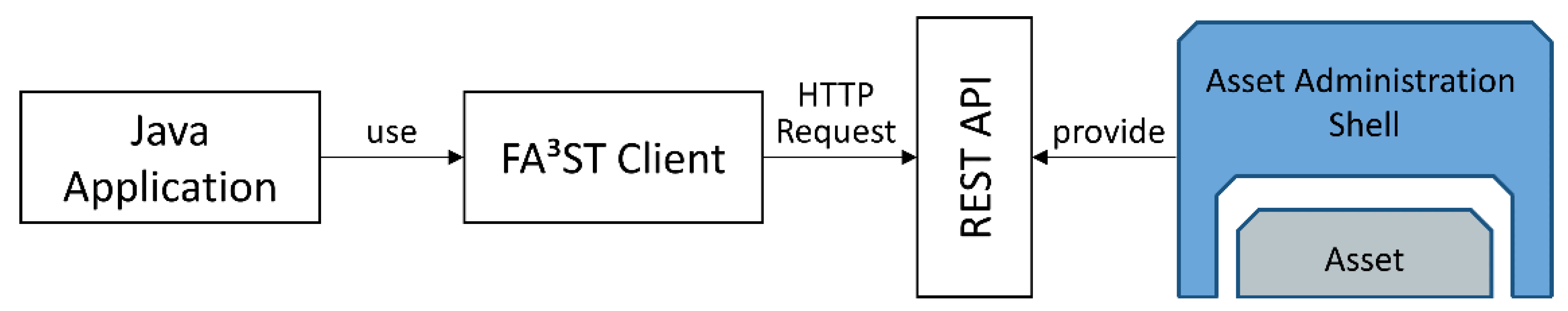
Currently, a FA3ST Java-based client library is in development. This standalone library can be used in other projects to interact with AAS services, according to the AAS API, as shown in Figure 10. By providing a client library, programming efforts for projects requiring interaction with the AAS can be significantly reduced; hence, raising adoption of the AAS standard.
4.9. FA3ST Manager
Once a company is using and validating its digital representations in the form of AASs, there is a need to continuously monitor the status and update the models according to the lifecycle phase. It is also important to keep a clear overview of all deployed services and models.
A software tool in FA3ST to help with this task is the “FA3ST manager”, which supports all standardized AAS implementations and provides an easy-to-use graphical abstraction for the end-user. For example, a filter and grouping function of similar AAS helps to quickly check on the relevant AAS. At the end of the lifecycle, an AAS service might be required to shut down. Since there are different implementations of the standard, and as the AAS API does not provide any means to start, stop, or restart an AAS [8], it is not possible to provide a universal start–stop solution. In the case of FA3ST, we are able to shutdown services, which are deployed in a docker environment. However, the manager would need extensions for other implementations to start or stop their services. For example, start and stop of the AASXServer would require such an extension. While the AASXServer provides a GUI to check on the deployed AAS, monitoring must be performed in other tools. In contrast to the Data and Service Portal of the digital twin platform described in [41], the FA3ST manager purpose is to monitor and update the DT services. The manager is not a search platform designed to find metadata or request data.
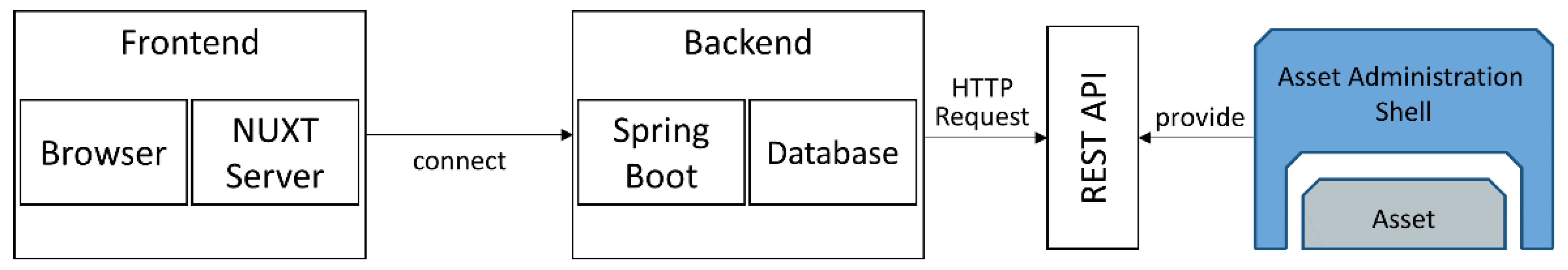
Figure 11 shows the implemented architecture for the FA3ST manager. For the connection between the manager backend and other FA3ST services, the AAS API is used. Relevant data from the services are then stored in the database, which can be any Java persistence API (JPA) [42] compatible database. The graphical interface in the frontend shows the status and notifications of the connected services.
For the FA3ST manager, it is also important to consider the resource intensiveness of realizing real-time status checks. Frequent requests to verify all elements are present in the AAS, which will lead to high load on the AAS and the network. In a productive environment with hundreds of AASs, there might be priority services, which is why the manager needs to be configurable to not overburden the network while maintaining its functionality. For the status refresh frequency, we can set values between seconds and days.
The filtering and search functions in the frontend make use of the data stored in the database. Additionally, the sorting and grouping attributes of several services will also be stored in the database. For this, the FA3ST manager supports the creation of hierarchical and flat relations between the services. This hierarchical and flat modelling of all available services leads to greatly improved overview and monitoring.
5. Use Case—Digital Twin of a Sorting Device
In this chapter, FA3ST is applied to access information on the current state of a sorting device to provide a practical example, specifically on how the already implemented tools of FA3ST can be used to create DTs in a production environment.
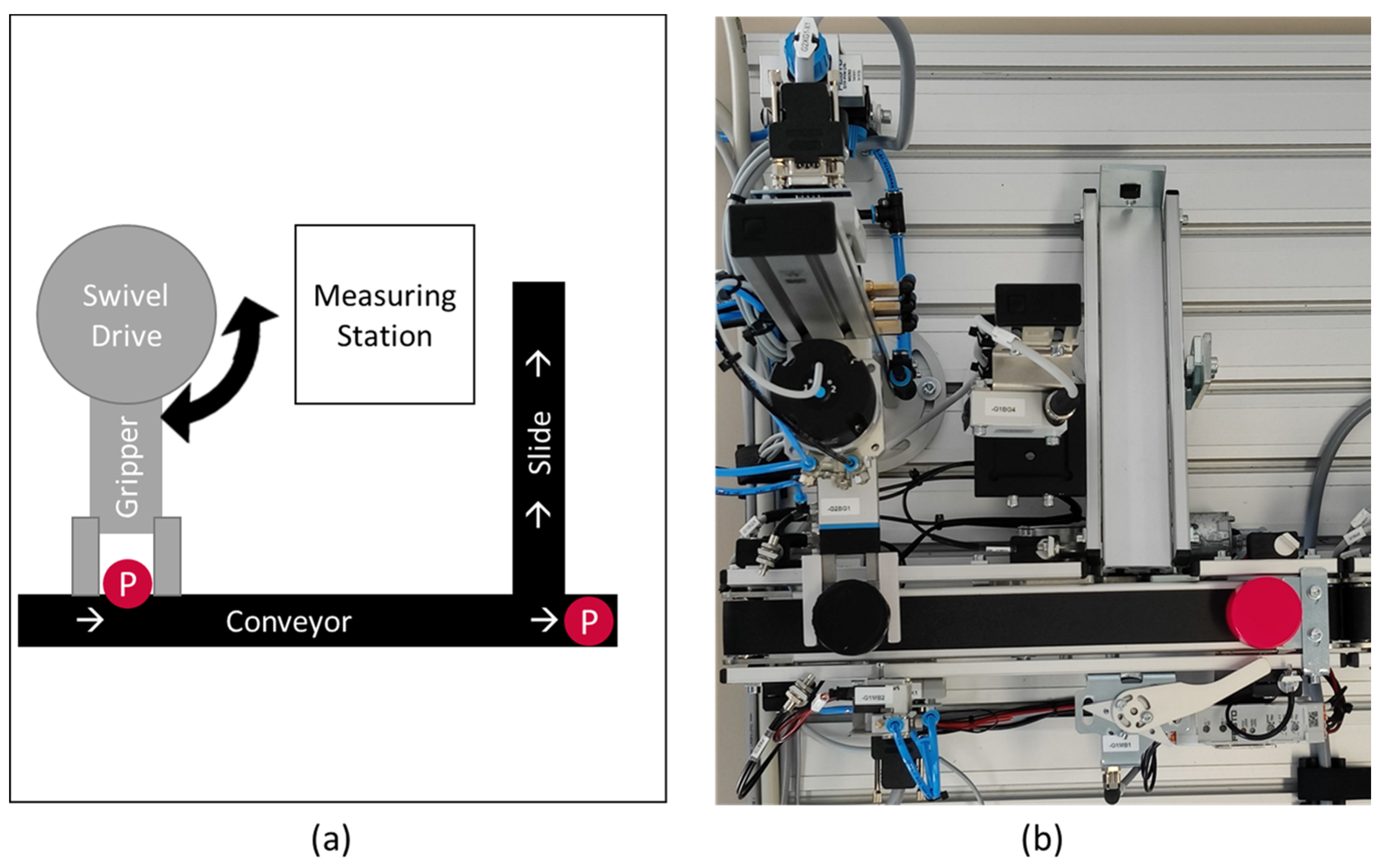
The demo setup, as shown in Figure 12, consists of a measuring station and a separating device which are connected by a conveyor belt. The measuring station determines the height of parts; parts which do not surpass the threshold height are removed from the system. The electro pneumatic system is equipped with several sensors, such as position and pressure sensors. This allows close monitoring of the systems behavior and measurements. For example, the time that an actuator needs to reach a desired position. Based on the information provided by these sensors, a PLC operates all devices in the system. Additionally, all sensor and actuator information are provided through an OPC UA server that is available on the network.
Our goal was to create a DT for this setup using FA3ST to show the whole lifecycle of a DT from start to end, as depicted in Figure 13. Once the mechanical setup and PLC programming was carried out, the resulting OPC UA server did not comply with any standard to model the station data.
Therefore, during the identification phase, we identified the most important data and configuration variables provided by the OPC UA server. Since the FA3ST model generator is not yet realized, the AAS for the sorting device was modeled manually and stored as JSON file. As shown in Listing 1, we re-used the FA3ST service and changed the JSON file to import our description of the measuring station. For each sub-model element of the AAS, we configured the corresponding OPC UA node, so that all station data are constantly synchronized into the AAS.
For unexperienced users, the FA3ST model generator and configurator, described in Section 4.1 and Section 4.4, respectively, can support the mapping and configuration of the software during the modelling and developing phase.
The FA3ST service was then registered in the FA3ST registry which means that we are now in the sharing phase. FA3ST services usually register automatically at start-up in the configured registry. During the configuration, we only have to specify the URL of the registry.
At this point, the DT is now running as a FA3ST service inside our Kubernetes deployment cluster and accepts connections over the AAS API. This means that the DT is now in the usage phase of its lifecycle. To provide a graphical interface, we deployed FA3ST visualization to visualize data from the AAS HTTPS endpoint, as previously shown in Figure 9. Lastly, we added the FA3ST service inside the FA3ST manager to monitor the DT and to easily update the AAS model. This can be necessary if a mismatch between the AAS model and the use case requirements is detected during the validation phase. In this situation, the DT is updated according to the lifecycle.
For secure data sharing between companies, an IDS DSC was deployed, as described in Section 4.6 on FA3ST secure data sharing. For this demonstrator, configuration to connect the FA3ST service to the DSC was performed manually; however, in the future, an automatic import of FA3ST services into the DSC will be possible via a FA3ST IDS app. With the DSC, we can allow other companies to use our DT while also keeping control of our station data by restricting the data usage with usage control.
6. Related Work
In this section, we analyze the related work on DT lifecycle management. The analysis of tool support for each phase of the DT lifecycle is described in Section 4.
In [2], the authors provided a state-of-the art survey of DT, considering two aspects: technical product lifecycle management and business innovation. The result of this work includes the identification of eight future perspectives for DTs as well as a guide to the state of the art of DT development and application. Some of the aspects identified are considered and further elaborated in our approach, such as a formal model to ensure model consistency.
In terms of DT engineering, the authors focus on DT perspectives in PLM phases, such as the design phase, the manufacturing phase, the distribution phase, the use phase, and the end-of-life phase. It also describes the role of DT technology in the different phases of PLM engineering. Since DTs can be developed for any observable asset (e.g., process, supply chain, etc.), the DT management approach proposed in this paper abstracts from production engineering and defines a model that can be applied to any asset.
Additionally, in [2], the main technological tools used in DT creation are highlighted. While this paper identified four essential categories (i.e., communication, representation, computation, and microservices) to form a technology stack that ensures a coherent and consistent DT implementation, we showed how this was realized based on the PI4.0 AAS specification, and discussed technical challenges.
A set of requirements for a DT framework based on the analysis of DT definitions is derived in [3]. The requirements, such as re-usability, extensibility, interoperability, etc., have already been considered when FA3ST was designed. The authors claim that, in order to ensure the fulfillment of the requirements and, thus, to provide a level of guaranteed DT capabilities, there is a need for either implicitly or explicitly support for a DT lifecycle. In this context, the paper proposes a high-level view of a common DT lifecycle. The lifecycle is split into offline development and online deployment and maintenance. In addition to steps in the lifecycle process, key decision points are also introduced.
The DT lifecycle models proposed in this paper and our approach are structured differently. Although it is not obvious at first sight, there are three feedback loops in both lifecycle models: the redesign of DT, the reconstruction of DT, and the improvement of its services. With regard to the phases of the DT lifecycle, we not only described the requirements in each phase, but also presented the technical challenges that need to be overcome. Furthermore, we described our tools for addressing these challenges. For example, in terms of DT reusability, we propose to the DT registry to make a DT discoverable, e.g., to use it for the creation of other DTs by instantiation or by combining DTs into a composite DT.
An adaptive and easy methodology to develop the DTs was proposed in [4]. It provides a systematic guideline to build DTs for manufacturing plant. There are many similarities between this methodology and the one we proposed, such as the initial phase, in which users provide input to formulate the DT problem. The difference lies in the means of implementing each phase. For example, while the methodology proposed in [4] explains what knowledge should be acquired (identifying the goal, constraints and key factors), we propose a structured approach to collect this knowledge in a formalized manner that can be used (semi-)automatically to build the DT model. In terms of the DT lifecycle model, our methodology envisions the sharing phase, where DTs should be made discoverable and accessible. This is mandatory to be able to create composite DTs. Additionally, this will significantly simplify the creation of DTs for concrete assets based on the DTs for the asset types.
In [9], the authors performed the detailed analysis of the state-of-the-art definitions of DT, the main characteristics that a DT should possess, and the exploration of the domains in which DT applications are currently being developed. Based on this study, the implications on the DT lifecycle are presented. The lifecycle of DTs includes all phases from design to dismissal. Compared to our approach, the identification phase of DTs is not considered, although it is essential for defining the scope of a DT. Similarly, no aspect related to modelling of DTs is addressed. On the other hand, our approach does not include the dismissal phase, as the focus is on the digital representation of an asset and not on a physical object that sometimes needs to be disassembled.
The paper also identified some important issues and challenges that need to be further investigated and addressed. In terms of technical limitations, the issues identified relate to the quality and reliability of the Internet connection and to the visualization of DT data. We consider that the former goes beyond the scope of DT management, since it concerns the infrastructure. As for the visualization, it is treated as a service of a DT. Due to the extensibility of the DT, it would be possible to add any visualization that meets the needs of the users.
7. Conclusions
We are now entering a more complex phase of digitalization in which the use of DTs is increasing rapidly. There is a growing need for a flexible approach to manage DTs by simplifying the complexity of all the tasks required by ensuring efficiency and consistency. In this paper, we discussed challenges for the engineering and management of DTs. Our intention is to conceptualize methods and tools that support the whole lifecycle of a DT, from identification to modelling, development, sharing, use, and continuous improvement. We presented the FA3ST toolkit as a representative implementation of a generic and flexible architecture for DT management that aims at a comprehensive functionality in its final stage. Such tools should flexibly connect to and/or build upon existing DT frameworks and, thus, form the basis to be used by a wide range of companies, even by those who already have proprietary implementation of DTs. As open architectures for smart manufacturing are key to solve interoperability issues, we argue that such tools shall be based upon emerging Industrie 4.0 standards, such as the AAS conceptual level and their technological mappings to OPC UA and AutomationML. These standards are more and more relevant, not only when exchanging data between physical assets, but also in the virtual world between DTs. Due to the integration of the mentioned standards and its extensibility, FA3ST can help to integrate physical devices into large-scale data analytics and simulation solutions, such as the platform approach proposed by the IoTwins consortium [43].
There is an increasing demand in industrial production to enable sustainability and resilience in supply chain networks [44], which means that DT ecosystems span across multiple organizations. In order to avoid depending on proprietary cloud-based environments, initiatives, such as GAIA-X, in combination with technologies of the IDS, are under development to maintain control over the usage of DT [45]. Future DT engineering and management architectures and tools shall be positioned in such environments.
Author Contributions
Conceptualization, L.S., T.U., F.V., C.W., J.M., M.J. and T.B.; software, F.V., C.W., J.M., M.J. and T.B.; investigation, L.S., T.U., F.V., C.W., J.M., M.J. and T.B.; writing—original draft preparation, L.S., T.U., F.V., C.W., J.M., M.J. and T.B.; writing—review and editing, L.S., C.W. and M.J.; visualization, L.S., T.U., F.V., C.W., J.M., M.J. and T.B.; supervision, L.S. and T.U.; project administration, L.S. and T.U.; funding acquisition, L.S. and T.U. All authors have read and agreed to the published version of the manuscript.
Funding
This research was partly funded by the H2020 COGNITWIN project, which has received funding from the European Union’s Horizon 2020 research and innovation programme under grant agreement No. 870130 and by the internal research project CrossTEP-DTE of Fraunhofer IOSB, Karlsruhe.
Conflicts of Interest
The authors declare no conflict of interest.
References
- Grieves, M. Origins of the Digital Twin Concept. 2016. Available online: https://www.researchgate.net/publication/307509727_Origins_of_the_Digital_Twin_Concept (accessed on 10 November 2021).
- Lim, K.Y.H.; Zheng, P.; Chen, C.-H.A. State-of-the-art survey of Digital Twin: Techniques, engineering product lifecycle management and business innovation perspectives. J. Intell. Manuf. 2020, 31, 1313–1337. [Google Scholar] [CrossRef]
- Moyne, J.; Qamsane, Y.; Balta, E.C.; Kovalenko, I.; Faris, J.; Barton, K.; Tilbury, D.M. A Requirements Driven Digital Twin Framework: Specification and Opportunities. IEEE Access 2020, 8, 107781–107801. [Google Scholar] [CrossRef]
- Latif, H.H. A Methodology for Developing Digital Twins in the Manufacturing Plant. 2020. Available online: https://repository.lib.ncsu.edu/handle/1840.20/38132 (accessed on 5 October 2021).
- Digital Twin Consortium. Glossary of Digital Twins. Available online: https://www.digitaltwinconsortium.org/glossary/glossary.html#digital-twin (accessed on 8 October 2021).
- Jacoby, M.; Jovicic, B.; Stojanovic, L.; Stojanović, N. An Approach for Realizing Hybrid Digital Twins Using Asset Administration Shells and Apache StreamPipes. Information 2021, 12, 217. [Google Scholar] [CrossRef]
- Plattform Industrie 4.0. Details of the Asset Administration Shell—Part 1 The Exchange of Information between Partners in the Value Chain of Industrie 4.0. (Version 3.0RC01). Available online: https://www.plattform-i40.de/IP/Redaktion/EN/Downloads/Publikation/Details_of_the_Asset_Administration_Shell_Part1_V3.pdf?__blob=publicationFile&v=5 (accessed on 5 October 2021).
- Plattform Industrie 4.0. Details of the Asset Administration Shell Part 2—Interoperability at Runtime—Part 2—Interoperability at Runtime—Exchanging Information via Application Programming Interfaces: (Version 1.0RC01). 2020. Available online: https://www.plattform-i40.de/IP/Redaktion/DE/Downloads/Publikation/Details_of_the_Asset_Administration_Shell_Part_2_V1.pdf?__blob=publicationFile&v=6 (accessed on 5 October 2021).
- Barricelli, B.R.; Casiraghi, E.; Fogli, D. A Survey on Digital Twin: Definitions, Characteristics, Applications, and Design Implications. IEEE Access 2019, 7, 167653–167671. [Google Scholar] [CrossRef]
- Minerva, R.; Lee, G.M.; Crespi, N. Digital Twin in the IoT Context: A Survey on Technical Features, Scenarios, and Architectural Models. Proc. IEEE 2020, 108, 1785–1824. [Google Scholar] [CrossRef]
- Jacoby, M.; Usländer, T. Digital Twin and Internet of Things—Current Standards Landscape. Appl. Sci. 2020, 10, 6519. [Google Scholar] [CrossRef]
- Plattform Industrie 4.0. Direkter Einstieg für Entwickler: Plattform Industrie 4.0 Veröffentlicht Aktualisierte Verwaltungsschalen-Spezifikation mit OPC UA-, AML- und RDF-Mapping. 2019. Available online: https://www.plattform-i40.de/IP/Redaktion/DE/Pressemitteilungen/2019/2019-11-25-VWS_SPS.html (accessed on 12 October 2021).
- OPC Foundation Unified Architecture—OPC Foundation. Available online: https://opcfoundation.org/about/opc-technologies/opc-ua/ (accessed on 14 October 2021).
- Bibow, P.; Dalibor, M.; Hopmann, C.; Mainz, B.; Rumpe, B.; Schmalzing, D.; Schmitz, M.; Wortmann, A. Model-Driven Development of a Digital Twin for Injection Molding. In Advanced Information Systems Engineering; Dustdar, S., Yu, E., Salinesi, C., Rieu, D., Pant, V., Eds.; Springer International Publishing: Cham, Switzerland, 2020; Volume 12127, pp. 85–100. [Google Scholar]
- Boss, B.; Malakuti, S.; Lin, S.W.; Usländer, T.; Clauer, E.; Hoffmeister, M.; Stojanovic, L.; Flubacher, B. Digital Twin and Asset Administration Shell Concepts and Application in the Industrial Internet and Industrie 4.0: An Industrial Internet Consortium and Plattform Industrie 4.0 Joint Whitepaper. 2020. Available online: https://www.plattform-i40.de/IP/Redaktion/EN/Downloads/Publikation/Digital-Twin-and-Asset-Administration-Shell-Concepts.html. (accessed on 5 October 2021).
- International Organization for Standardization. Automation Systems and Integration—Digital Twin Framework for Manufacturing—Part 2: Reference Architecture 25.040.40; 35.240.50(ISO 23247-2:2021). 2021. Available online: https://www.iso.org/standard/78743.html (accessed on 12 October 2021).
- Malakuti, S.; van Schalkwyk, P.; Boss, B.; Sastry, C.R.; Runkana, V.; Lin, S.W.; Rix, S.; Green, G.; Baechle, K.; Nath, C.V. Digital Twins for Industrial Applications—Definition, Business Values, Design Aspects, Standards and Use Cases: An Industrial Internet Consortium White Paper. 2020. Available online: https://www.iiconsortium.org/stay-informed/digital-twins-for-industrial-applications.htm (accessed on 12 October 2021).
- GO FAIR. FAIR Principles—GO FAIR. 2021. Available online: https://www.go-fair.org/fair-principles/ (accessed on 12 October 2021).
- Suhail, S.; Hussain, R.; Jurdak, R.; Hong, C.S. Trustworthy Digital Twins in the Industrial Internet of Things with Blockchain. IEEE Internet Comput. 2021, 1–8. [Google Scholar] [CrossRef]
- Jacoby, M.; Volz, F.; Weißenbacher, C.; Stojanovic, L.; Usländer, T. An Approach for Industrie 4.0-compliant and Data-Sovereign Digital Twins. Automatisierungstechnik 2021, 69. (in press). [Google Scholar] [CrossRef]
- Bonhage, M.; Wilkens, R.; Denkena, B.; Kemp, D. Der digitale Zwilling als Basis für ein intelligentes und skalierbares Produktionssystem. SPS Mag. 2021, 6, 61–63. [Google Scholar]
- Laemmle, A.; Gust, S. Automatic layout generation of robotic production cells in a 3D manufacturing simulation environment. Procedia CIRP 2019, 84, 316–321. [Google Scholar] [CrossRef]
- Schmidt, N.; Lüder, A. AutomationML in a Nutshell. 2015. Available online: https://www.automationml.org/wp-content/uploads/2021/06/AutomationML-in-a-Nutshell_151104.pdf. (accessed on 5 October 2021).
- International Electrotechnical Commission—IEC. Engineering Data Exchange Format for Use in Industrial Automation Systems Engineering—Automation Markup Language—Part 1: Architecture and General Requirements (IEC 62714-1:2018). 2018. Available online: https://webstore.iec.ch/publication/32339 (accessed on 5 October 2021).
- TIA Portal Openness: Automation of Engineering Workflows. Available online: https://support.industry.siemens.com/cs/document/109792902/tia-portal-openness-automation-of-engineering-workflows?dti=0&lc=en-WW (accessed on 16 October 2021).
- Hämmerle, H.; Strahilov, A.; Drath, R. AutomationML im Praxiseinsatz. atp Mag. 2016, 58, 52–64. [Google Scholar] [CrossRef]
- OPC Foundation OPC UA Information Models—OPC 30270 UA for I4 Asset Administration Shell. Available online: https://opcfoundation.org/developer-tools/specifications-opc-ua-information-models/opc-ua-for-i4-asset-administration-shell/ (accessed on 5 October 2021).
- Eclipse Foundation Eclipse BaSyx. Available online: https://www.eclipse.org/basyx/ (accessed on 8 October 2021).
- Apache StreamPipes. Available online: https://streampipes.apache.org/ (accessed on 14 October 2021).
- Admin-Shell-io/aasx-server: C# Based Server for AASX Packages. Available online: https://github.com/admin-shell-io/aasx-server (accessed on 8 October 2021).
- Industrial Digital Twin Association e.V. IDTA—Der Standard für den Digitalen Zwilling. Available online: https://industrialdigitaltwin.org/ (accessed on 8 October 2021).
- Di Orio, G.; Malo, P.; Barata, J. NOVAAS: A Reference Implementation of Industrie4.0 Asset Administration Shell with best-of-breed practices from IT engineering. In Proceedings of the IECON 2019—45th Annual Conference of the IEEE Industrial Electronics Society, Lisbon, Portugal, 14–17 October 2019; Volume 45, pp. 5505–5512. [Google Scholar]
- NOVA Asset Administration Shell-Repository. Available online: https://gitlab.com/novaas/catalog/nova-school-of-science-and-technology/novaas (accessed on 5 October 2021).
- BaSyx Documentation Registry. Available online: https://wiki.eclipse.org/BaSyx_/_Documentation_/_Registry (accessed on 5 October 2021).
- International Data Spaces e.V. IDS Reference Architecture. Available online: https://internationaldataspaces.org/use/reference-architecture/ (accessed on 8 October 2021).
- International Data Spaces e.V. Usage Control in the IDS. 2021. Available online: https://internationaldataspaces.org/wp-content/uploads/dlm_uploads/IDSA-Position-Paper-Usage-Control-in-the-IDS-V3.0.pdf (accessed on 8 October 2021).
- International Data Spaces e.V. IDSA Industrial Community. 2019. Available online: https://internationaldataspaces.org/idsa-industrial-community/ (accessed on 10 November 2021).
- Haße, H.; van der Valk, H.; Weißenberg, N.; Otto, B. Shared Digital Twins: Data Sovereignty in Logistics Networks. In Proceedings of the New Ways of Creating Value in Supply Chains and Logistics—Hamburg International Conference of Logistics (HICL), Hamburg, Germany, 23–25 September 2020. [Google Scholar]
- International Data Spaces e.V. DataspaceConnector Documentation. Available online: https://international-data-spaces-association.github.io/DataspaceConnector/ (accessed on 8 October 2021).
- International Data Spaces e.V. IDS Certification Position Paper. Available online: https://internationaldataspaces.org/use/certification/ (accessed on 8 October 2021).
- Redeker, M.; Weskamp, J.N.; Rössl, B.; Pethig, F. A Digital Twin Platform for Industrie 4.0. In Data Spaces: Design, Deployments, and Future Directions; Springer: Berlin, Germany, 2021; (accepted for publication). [Google Scholar]
- Eclipse Foundation JPA (Jakarta Persistence API). Available online: https://jakarta.ee/specifications/persistence/ (accessed on 8 October 2021).
- Costantini, A.; Duma, D.C.; Martelli, B.; Antonacci, M.; Galletti, M.; Tisbeni, S.R.; Bellavista, P.; Modica, G.D.; Nehls, D.; Ahouangonou, J.C.; et al. A Cloud-Edge Orchestration Platform for the Innovative Industrial Scenarios of the IoTwins Project. In Computational Science and Its Applications—ICCSA 2021, Proceeding of the 21st International Conference on Computational Science and its Applications, Part VIII, Cagliari, Italy, 13–16 September 2021; Gervasi, O., Murgante, B., Misra, S., Garau, C., Blečić, I., Taniar, D., Apduhan, B., Rocha, A.M., Tarantino, E., Torre, C.M., Eds.; Springer International Publishing: Cham, Switzerland, 2021; Volume 12950, pp. 533–543. [Google Scholar]
- Usländer, T.; Schöppenthau, F.; Schnebel, B.; Heymann, S.; Stojanovic, L.; Watson, K.; Nam, S.; Morinaga, S. Smart Factory Web—A Blueprint Architecture for Open Marketplaces for Industrial Production. Appl. Sci. 2021, 11, 6585. [Google Scholar] [CrossRef]
- International Data Spaces e.V. GAIA-X and IDS: Position Paper. 2021. Available online: https://internationaldataspaces.org/new-idsa-publication-crystallizes-shared-approach-with-gaia-x/ (accessed on 10 November 2021).
Figure 1.
Conceptual view on digital twins.

Figure 2.
The DT lifecycle.

Figure 3.
FA3ST tools for realizing the DT lifecycle.

Figure 4.
AAS is derived from software tools in the engineering environment.

Figure 5.
AAS Mapping Tool.

Figure 6.
Concept of the OPC UA Crawler.

Figure 7.
High-level schematic component diagram of the FA3ST service.

Figure 8.
User interacting with an AAS-compliant DT protected via IDS.

Figure 9.
An example of the FA3ST visualization using demo data.

Figure 10.
FA3ST HTTP Client.

Figure 11.
High-level architecture of the FA3ST manager.

Figure 12.
The figure illustrates the FA3ST demo setup. (a) a schematic representation of the real setup, showing how the gripper is picking products (P) from the conveyor and transporting them between the conveyor and the measuring station. (b) depicts the physical demo setup used in the use case, as described in Section 5.

Figure 13.
Subset of FA3ST applied to create a DT for the demo use case.

Publisher’s Note: MDPI stays neutral with regard to jurisdictional claims in published maps and institutional affiliations. |
© 2021 by the authors. Licensee MDPI, Basel, Switzerland. This article is an open access article distributed under the terms and conditions of the Creative Commons Attribution (CC BY) license (https://creativecommons.org/licenses/by/4.0/).
Share and Cite
MDPI and ACS Style
Stojanovic, L.; Usländer, T.; Volz, F.; Weißenbacher, C.; Müller, J.; Jacoby, M.; Bischoff, T. Methodology and Tools for Digital Twin Management—The FA3ST Approach. IoT 2021, 2, 717-740. https://doi.org/10.3390/iot2040036
AMA Style
Stojanovic L, Usländer T, Volz F, Weißenbacher C, Müller J, Jacoby M, Bischoff T. Methodology and Tools for Digital Twin Management—The FA3ST Approach. IoT. 2021; 2(4):717-740. https://doi.org/10.3390/iot2040036
Chicago/Turabian StyleStojanovic, Ljiljana, Thomas Usländer, Friedrich Volz, Christian Weißenbacher, Jens Müller, Michael Jacoby, and Tino Bischoff. 2021. "Methodology and Tools for Digital Twin Management—The FA3ST Approach" IoT 2, no. 4: 717-740. https://doi.org/10.3390/iot2040036