The GATE-RTion/IDEAL Independent Dose Calculation System for Light Ion Beam Therapy
 L. Grevillot1*†
  D. J. Boersma1,2†
  H. Fuchs1,3
  M. Bolsa-Ferruz1,3
  L. Scheuchenpflug1,4
  D. Georg3
  G. Kronreif2
  M. Stock1
- 1MedAustron Ion Therapy Center, Wiener Neustadt, Austria
- 2ACMIT Gmbh, Wiener Neustadt, Austria
- 3Department of Radiation Oncology, Medical University of Vienna, Vienna, Austria
- 4Isotope Physics, Faculty of Physics, University of Vienna, Vienna, Austria
Patient specific quality assurance can be improved using an independent dose calculation system. In addition, the implementation of such a system may support light ion beam therapy facilities in reducing the needs for beam time, by substituting some of the experimental patient-specific quality assurance procedures by independent dose calculation. The GATE-RTion-based IDEAL system for light ion beam therapy was developed for this purpose. It was built in a DICOM-in, DICOM-out fashion, for easy integration into a state-of-the-art technology-based workflow for scanned ion beam therapy. This article describes the IDEAL system, followed by its clinical implementation at MedAustron for proton and carbon ion beams. Medical physics acceptance and commissioning steps are presented together with key results: for 3D proton and carbon ion reference boxes, 97% of the points agreed within 5% from the measurements. Experimental validation of stopping powers using real pig samples were between 1.8% and 3.8% for soft tissues. Finally, five clinical cases are described, i.e. two proton and three carbon ion treatments. Dosimetric benchmarking against TPS calculations are presented and discussed in details. As expected, the IDEAL software evidenced limitations arising from the pencil beam algorithm available in the TPS for carbon ions, especially in the presence of air cavities. The IDEAL system was found to satisfy the clinical requirements for independent dose calculation of scanned ion beam delivery systems and is being clinically implemented at MedAustron. The open-source code as well as the documentation was released on the OpenGATE collaboration website, thus allowing for long term maintenance and future upgrades based on a more widespread utilization.
Introduction
Light Ion Beam Therapy (LIBT) is an advanced form of radiation therapy. While proton therapy is a more widespread technology, dual particle facilities equipped with both protons and carbon ions, such as MedAustron, are only six worldwide1. Clinically other types of ions may be of interest, however this article focuses on the particles and technology currently available at MedAustron, which are scanned proton and carbon ion beams [1]. Scanned ion beam therapy consists in scanning a small pencil beam laterally in the Planning Target Volume (PTV), while sparing the surrounding Organs At Risks (OARs) as much as possible. The distal conformation of the tumor is ensured by adjusting the beam energy and hence its range into the patient for each pencil beam delivered. Treatment planning is the key process to prepare the treatment. It necessitates a 3D CT scan of the patient anatomy acquired in the treatment position. PTVs, OARs and any other necessary Region Of Interest (ROI) are then delineated in the CT images and then the treatment plan is prepared. This article addresses the specific issue of the Patient-specific Quality Assurance (PSQA) process, after the treatment planning is completed.
PSQA can either be performed via measurements or via Independent Dose Calculation (IDC) system. The main advantage of the measurements is to include the verification of the beam delivery workflow. However, experimental PSQA suffers several limitations: 1) measurements are usually performed in a homogeneous phantom, which is not representative of the patient anatomy, therefore potential limitations of dose computation algorithms in patient anatomy cannot be verified; 2) QA is limited to a few measurement positions; 3) the set-up is fixed in the room and does not allow to check the patient positioning workflow; 4) it requires beam time for each plan to be irradiated, thus limiting the patient throughput and treatment planning adaptation. The main draw-back of IDC-based PSQA, is to exclude the treatment delivery and patient positioning workflow verification in the room. However, in contrast to the points 1, 2, 3, and 4 mentioned previously, the IDC is performed virtually in the full 3D patient geometry, simulating the beam delivery and patient positioning independently of the Treatment Planning System (TPS) at no beam time cost. Assuming LIBT centers implement comprehensive beam delivery and in-room equipment (patient positioning and verification systems) QA programs, IDC-based PSQA is a valid measure to complement or even substitute part of the experimental PSQA. According to ICRP112 [2], on the prevention of accidental exposure from new external beam radiation therapy technology, the “Calculation of the number of MUs for each patient independently from the TPS would have avoided most of the major accidental exposures resulting from the misuse of a TPS.” (where MU stands for Monitor Units). Over the last decade, several groups have been working on the development and implementation of IDC systems, mostly for scanned proton beams. Different home-made implementations have been proposed and developments were usually tailored by facility specificities [3–6]. The implementation of a Monte Carlo (MC) algorithm in an IDC system was shown to illuminate dose computation issues from analytical algorithms implemented in TPS, which would not otherwise be detected using traditional experimental PSQA [7]. However, it is generally recognized that IDC as such, i.e. the recomputation of a plan exported by the TPS using an IDC system, only allows to check TPS dose computation errors, but cannot detect beam delivery failures or data transfer corruption. For this reason, several groups have worked on the combination of IDC systems with machine steering files and/or treatment log-files [7–11]. With respect to LIBT, for ions heavier than protons, much less literature is available. Some dedicated codes are under development, either analytical [12] or MC-based [13]. An easy-to-use particle therapy platform based on FLUKA and supporting IDC functionality, biological dose calculation as well as dose-averaged LET distributions prediction for scanned proton and carbon ion beams was presented in [14]. Alternatively, GATE-RTion: a GATE/Geant4 release for clinical applications in scanned ion beam therapy [15] is available. It was validated for protons and carbon ions [5, 6, 16–19] and developed to make the bridge between researchers and clinical users in facilities equipped with scanned ion beam delivery systems. Fragmentation spectra of both FLUKA and Geant4 have been validated in the past [20] and found compatible for clinical use. More recently, it was shown that FLUKA vs. Geant4-based particle spectra resulted in RBE-weighted dose deviation of less than 1% in average in the entrance up to the end of the target region, with larger deviations in the distal fall-off and the tail of up to 3% and 5%, respectively [21].
This paper presents the GATE-RTion-based Independent DosE cAlculation system for LIBT (IDEAL). It was developed in a collaboration between the Medical University of Vienna, the Austrian Center for Medical Innovation and Technology and the MedAustron ion therapy center. First, the software architecture and implementation details are described. Second, the clinical implementation strategy as performed at MedAustron for scanned proton and carbon ion beams is presented. The result section includes a brief review of the installation, configuration and acceptance testing, followed by key medical commissioning results (beam modeling and CT calibration). Finally, five patient treatments (2 protons and 3 carbon ions) are retrospectively evaluated using IDEAL for typical indications treated at MedAustron.
Materials and Methods
IDEAL System Description
IDEAL V1.0 was released2 on March, 23rd, 2021, using GATE-RTion V1.0 [15] as dose engine. IDEAL was built as a wrapper around GATE-RTion, in a DICOM-in/DICOM-out fashion. The aim was that IDEAL should be easy to integrate into state-of-the-art technology, but in a vendor independent fashion, for scanned ion beam therapy facilities (Figure 1). TPS DICOM files are exported to IDEAL to run an IDC. IDEAL output DICOM dose files together with the TPS DICOM dose files can then be imported into any other clinical software for dose review and/or comparison.
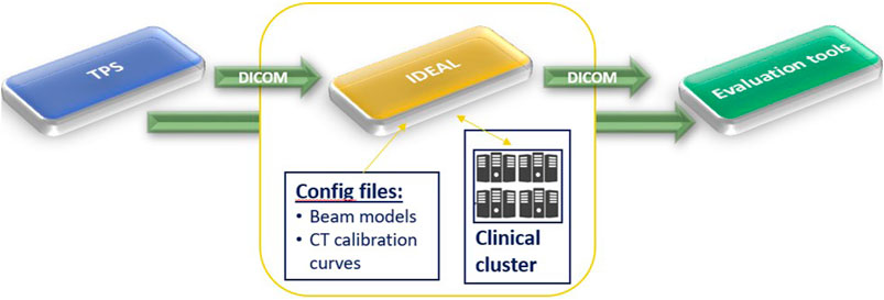
FIGURE 1. High level workflow of IDEAL. It shows that IDEAL was conceived in a DICOM-in/DICOM-out fashion, to ease the use of GATE-RTion for IDC in LIBT.
In the following sections, the description of the most relevant features and implementation details of IDEAL are provided, however the full documentation of IDEAL is available online3. GATE/Geant4 [22, 23] specific features will also be briefly presented, however for full details the reader is invited to read the GATE documentation, as well as the corresponding papers cited in the upcoming sections.
Synopsis
IDEAL is designed to run on a GNU/Linux cluster in order to provide simulation results within a reasonable time (e.g. less than 2 h). IDEAL is implemented as a set of python modules and scripts, which convert the information from the input TPS DICOM files (PLAN, DOSE, STRUCT and CT) into a set of files and scripts that can be used to run GATE-RTion. Beam models, nozzle geometry and CT calibration curves must be configured during installation and commissioning. Two interfaces are available: a graphical user interface (socrates.py) and a command line interface (clidc.py). The dose grid is by default the same as used by the TPS, but a different spatial resolution can be defined by overriding the number of voxels per dimension. Each of the beam dose distributions as well as the plan dose distributions can be stored as DICOM dose file.
Device-Oriented Workflow
A device oriented workflow is shown in Figure 2. In the following, the enumeration refers to the parenthesized numbers in the figure.
1) The DICOM treatment files from the TPS are exported to a shared file system, which is also mounted on the submission node of the cluster.
2) After logging into the submission node (typically with a generic secure shell utility) the user starts the independent dose calculation: the treatment plan file must be selected and a goal set (number of primaries, average uncertainty or a fixed calculation time).
3) IDEAL retrieves the plan file and all referred data (structure set, CT and TPS dose files).
4) A GATE simulation folder is populated with macros, input data, and configuration data, based on the treatment plan data and the clinic-specific configuration data (which are provided by the user during installation and commissioning). The beam model, CT calibration curve and output dose resolution are selected based on the input data, but can be overridden in the user interface.
5) Scripts are created to run an instance of GateRTion on each core of the cluster. Each beam in the input plan will be run using the HTCondor4 job management system. E.g. for a plan with two beams and a cluster with 48 nodes, 96 jobs will run. Additional scripts are generated to perform the pre- and post-processing steps (described below).
6) The “Directed Acyclic Graph manager” (DAGman) is a meta-scheduler for HTCondor, which is used to sequentially run first the preprocessing script, then (concurrently) the simulation jobs, and finally the post-processing script. After submitting the DAGman job, a job control daemon (a daemon is a computer program that runs as a background process) is started on the submission node.
7) The simulation is configured in such a way that most of the time all cores are simulating the same beam.
8) Each job saves the intermediate dose distribution and the simulation statistics (including the number of simulated primaries). The job control daemon periodically reads the intermediate results and checks whether the goal has been reached. Once this is the case, a semaphore file is created that will cause the StopOnScript actor from GATE to terminate the simulation.
9) The post-processing script accumulates the results and converts them to DICOM.
10) The results are copied to the shared folder.
11) The user imports the results back into a third party system for further analysis.
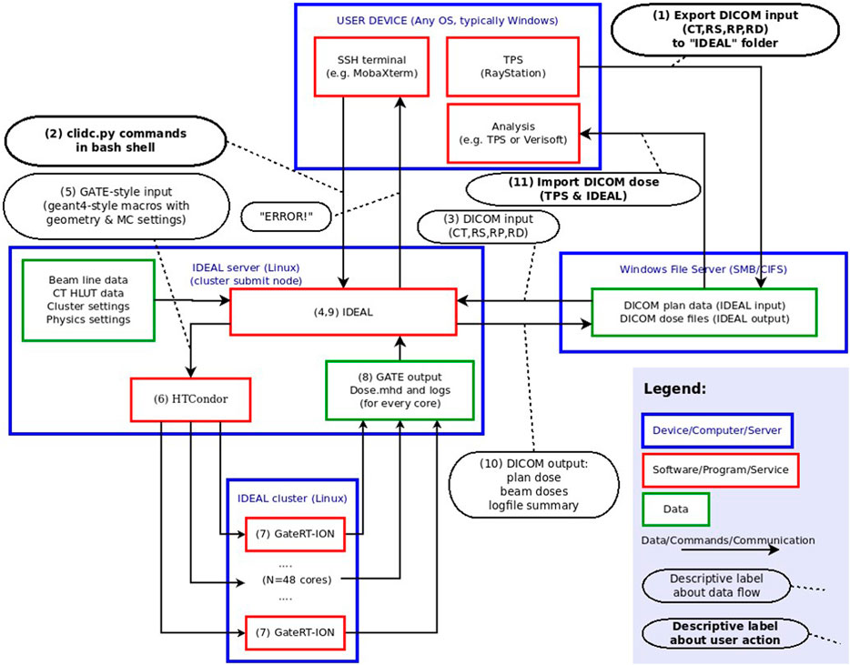
FIGURE 2. Device-oriented workflow of IDEAL. This figure describes from a technical view-point the different modules implemented in the IDEAL software to allow for GATE-RTion-based IDC in LIBT. The numbers in parentheses are used in the text to describe the workflow in more detail.
Pre-processing
The external ROI of the CT (i.e. the contour describing the external contour of the “patient anatomy”, including potentially boluses and contention mask, if any) is padded with a 10 mm thickness of air (“air box margin”) on all six sides. This air-padding aims at improving the correctness of the skin dose calculation. The bounding box is enclosing both the padded external ROI of the CT and the TPS dose distribution. The CT image is then cropped to fit the bounding box. Any voxel whose central point is not within the external ROI is overridden with air (G4_AIR). Hounsfield Unit (HU) values are truncated to the maximum HU value specified in the relevant CT protocol. ROI overrides specified by the user are applied to each voxel whose central point lies within the specified ROI. The material overrides are implemented by extending a copy of the interpolated CT calibration curve: in the extension, HU values larger than the initial maximum HU value are generated and associated with the override materials. A dose mask file is created with the same geometry as the output dose files, with value 1 (or 0) for all voxels with the central point inside (or outside) the external ROI, in order to limit the dose output to within the external ROI, if specified by the user.
GATE-RTion Simulation
By convention a Gate work directory has 3 subfolders: mac (Gate/Geant4 macro), data (any input files that are not macro files) and output (simulation outputs). As IDEAL simulates each beam separately, there is a main macro file for each beam. Assuming a treatment plan with 3 beams running on a cluster with 50 physical cores, 150 output directories would be created. The corresponding output directories are suffixed with the job number.
Geometry: CT or Phantom
The geometry for the simulation is defined in such a way that the isocenter coincides with the origin in the Geant4 coordinate system. A patientbox volume is defined as the smallest rectangular box that is centered on the isocenter and contains the bounding box described earlier. The material for the world and patientbox volumes is G4_AIR. The cropped CT image is imported into Gate using the ImageNestedParametrisedVolume geometry element defined by GATE/Geant4 as a daughter volume of the patientbox. Using the TranslateTheImageAtThisIsoCenter command with the isocenter coordinates taken from the DICOM plan data, the CT image is translated with respect to the origin of the patientbox. The couch rotation is performed on the patientbox. For commissioning purposes, it can be useful to run the simulation on a geometrically defined phantom instead of a CT image. To this end, phantoms can be defined during commissioning. The planned couch angle has no effect on the positioning of such phantoms.
HU to Material Definition
For each CT protocol, 2 calibration curves are required: HU to density and HU to composition. GATE provides a HounsfieldMaterialGenerator tool to interpolate these 2 curves using the density tolerance parameter ( [22] for more details) and generate the CT calibration input files needed for GATE. While the initial implementation for GATE was based on the well-established Schneider method [23]; alternative calibration files could be defined. IDEAL automatically selects the CT protocol based on some criteria, which are configurable. If a CT protocol is used for the first time, the CT calibration input files are generated and saved in the cached folder in order to be re-used in future. Any change to the input density and composition calibration files, as well as on the density parameter, will trigger a new generation of CT calibration input files in the cached folder.
Beam Delivery Description
For each treatment machine (beam line), GATE macro files describing the available passive elements (range shifters, ripple filters, etc.) for that beamline are required [19]. A physical description of the nozzle geometry (beam monitors, vacuum windows, exit window, etc.) may be optionally provided. The DICOM treatment plan is converted into a treatment plan file, which together with the source description file, are used as the 2 key inputs for the GateSourceTPSPencilBeam to simulate the beam delivery ([24] for more details). Beam optics and energy properties from all spots in the beam are randomly sampled, with probabilities proportional to the number of planned particles per spot, and Gaussian distributions given by the source description file.
Physics Settings and Dose Computation
Different physics builders can be configured for protons and carbon ions. In addition, typical simulation settings (e.g.: cut, step size) can be set-up as a compromise between speed and accuracy [5]. The dose scoring is handled by the so-called DoseActor attached to the cropped CT image, using the mass weighting algorithm, which is the most accurate method available in GATE for scoring the dose [25]. Depending on the settings, the dose to medium or the dose to water are scored using the resolution of the CT [26]. Intermediate results are saved periodically during the simulation (default every 300 s) as mhd files. The job control daemon and post-processing script monitor and resample the intermediate dose outputs to the specified final dose output resolution.
Uncertainty Goal
The job control daemon computes an estimate of the Type A uncertainty in each resampled voxel when resampling the intermediate dose distributions. A mean maximum value of dose-per-primary is estimated by computing the mean of the Ntop (default = 100) highest values in the distribution. A threshold value is defined as a fraction P (default 50%) of this mean maximum. The average uncertainty is computed as the average of the relative uncertainties of those voxels having a dose-per-primary higher than this threshold.
Post-processing
IDEAL accumulates the dose distributions and total number of primaries from all simulated beams on all cluster cores and scale the dose with the ratio of the planned and simulated number of primary particles. A dose scaling factor can also be applied, if configured. The dose scaling factor allows for correcting systematic dose deviations observed between simulations and measurements. Finally, IDEAL resamples the beam doses to the specified resolution. For protons, the effective dose is computed by scaling the physical dose by a constant factor (typically 1.1). If configured, the system will also compute the plan doses (physical and effective for protons, physical only for carbon ions). The user log summary text file with settings and performance data is updated. Outputs (beam and plan dose files, user log summary) are copied on a Windows shared folder (if configured). The outputs from all Gate-RTion simulations are compressed and temporary copies removed.
Acceptance and Commissioning
Acceptance Testing
The clinical implementation of IDEAL was divided into several steps. An acceptance testing protocol was carried out in order to verify that the system complies with all requirements and to validate the system installation and configuration at the MedAustron ion therapy facility.
Beam Modeling
Beam modeling was carried out by modeling the full MedAustron nozzle [1], in order to have the most accurate beam models, including nuclear secondaries produced in the nozzle. The validation of the proton horizontal fixed beam line was presented in [16]. Beam modeling of the subsequent proton and carbon ion beamlines was automated using the tools and procedures described in [27]. The beam models were used as input to calibrate the MedAustron beam delivery monitors (so called Dose Delivery System) in absolute number of particles per monitor unit in reference conditions [28]. Therefore, the beam models are intrinsically calibrated in number of particles per monitor unit in reference conditions. However, due to various sources of uncertainties, calibration in reference conditions does not necessarily mean that the beam model output in 3D generated SOBP has the same accuracy. Therefore, the beam models were subsequently validated in 3D and scaling factors for proton and carbon ion beam models were defined.
Dosimetric Commissioning in Water
The beam modeling validation followed a similar procedure as for TPS commissioning in water [29], using the so called 3D-block (PTW, Freiburg, Germany), equipped with 24 PinPoint ionization chambers type 31015 (PTW, Freiburg, Germany). Dose deviations were always normalized to the maximum predicted dose. Simulation pass rates against the PinPoint measurements taken as reference were evaluated considering the 3%, 5% and 7% dose difference criteria (normalized to the maximum predicted dose). In addition, signed and unsigned mean dose deviations (again normalized to the maximum predicted dose and considering all measurement points for the corresponding treatment plan) were provided.
The proton horizontal beam model was validated in details: target of different shapes and complexity were considered (square, cylinder, H-shape etc.), using different air gaps (at isocenter (ISD0) or at a non-isocentric reference point 50 cm upstream isocenter (ISD50) for horizontal beam lines), with or without range shifter. These treatment plans included field sizes from 3 to 20 cm, from 0.03 to 2-liter volumes and more, centered between 3 and 31 cm depth.
Based on the proton horizontal beam model validation experience, a similar procedure was applied to the carbon ion horizontal beam model, but for a restricted subset of four key reference targets: Box6_ISD0 (0.2 L), Box8_ISD0 (0.5 L) and Box10_ISD0 (1 L) at isocenter, as well Box6_ISD50_RS (0.2 L) with range shifter at non-isocentric reference position ISD50. The reference boxes 6/8/10/6_RS were centered at 6/15/25/5 cm and 6/13/21.8/5 cm, for protons and carbon ions, respectively.
Vertical beam models were only tested during acceptance testing. Except otherwise specified, simulations were run using a 2 mm scoring grid and a 1% statistical uncertainty goal. The Toolkit for the Evaluation of Dicom Doses (TEDD) developed to support the dosimetric commissioning process was described in [30].
CT Calibration and Validation
Six CT protocols are used clinically for patient treatment: three for adults and three for pediatric cases. The CT calibration was performed using slabs of tissue-equivalent materials from CIRS. The lightest tissue-like material was lung-like starting with a density of 0.195 g/cm3 and the densest bone-like material was 2.7 g/cm3. The exact same measurements initially used for the commissioning of the TPS were used to commission the CT curves in IDEAL. A total of eight different tissue-like materials were used. All protocols were calibrated following the stoichiometric calibration from Schneider [23]. The CT validation was performed by comparison of Water Equivalent Thickness (WET) measurements of pig tissues [31] against IDEAL and TPS simulations, using a 160-MeV proton beam. A total of 10 tissue samples (lung, adipose, brain, kidney, heart, blood, spleen, liver, muscle, bone) were inserted in an 8-cm thick phantom (in the beam direction). A CT scan of the tissue phantom was performed using 2 CT protocols (adult-abdominal and adult-head). The median HU value of each ROI for the different tissues was calculated and converted into density. For simplicity, two main ROIs were afterwards created: a cylinder of 6 cm diameter and 8 cm length in front of a 50-cm cubic box. In the TPS, the cylinder was overridden with the tissue densities and the corresponding ICRU material that are provided to represent real tissues [32]. In IDEAL, the cylinder was overridden with the Schneider material whose HU range included the calculated median HU. The densities of the chosen Schneider materials differed by 0.1% in average from the real tissue densities. The box was overridden with water.
Clinical Examples
Five clinical treatment plans were selected to evaluate the capabilities of IDEAL (Table 1). Two treatments with protons (patients P1 and P2) and three treatments with carbon ions (patients C1, C2, C3). The TPS used was RayStation 8B (RaySearch Laboratories, Stockholm, Sweden). Proton treatment plans were computed using the MC algorithm version 4.2, using a statistical uncertainty of 0.5%. Carbon ion treatment plans were computed using the pencil beam algorithm version 3.0. Proton treatments were always planned without ripple filters (RiFis) in non-isocentric conditions (i.e. the patient is shifted towards the nozzle), as explained in [28]. Carbon ion treatment beams were always planned with RiFis, which are a necessary accessories for carbon ion therapy [19] in isocentric condition, except when the range shifter (RS) was used in addition, in which case the patient was shifted towards the nozzle as for proton treatments. Different target volumes were simulated, from 71cc up to 1.1 L. Different treatment locations were evaluated, such as para-nasal cavities, abdomen and pelvic regions. Typically, the CT protocol for head has a slice thickness of 2 mm and the abdomen/pelvic protocols have a slice thickness of 3 mm. A combination of horizontal beams (HBL) and vertical beams (VBL) were used. All treatment plans used the so called Multiple Field Optimization Technique (MFO) as defined in Ref. [33], i.e. each beam delivered a non-homogeneous dose to the target. Different doses per fraction were applied: from 1.8 Gy per fraction up to 7.5 Gy per fraction. Treatments reporting more than one PTV indicated the usage of a so called Simultaneously Integrated Boost (SIB) technique [34], i.e. a different dose per fraction applied to the different PTVs in the same treatment plan (e.g. P1 and P2). All selected treatment plans were evaluated retrospectively. The TPS DICOM treatment plan files (Plan, Structure, CT, Physical and Effective Doses of the Plan and Beams) were exported without anonymizing the data. IDEAL was run on a cluster using a single command line (clidc.py -l “username” -u “uncertainty goal” “MyPlan.dcm”) for each patient specifying the uncertainty goal to 1% for each beam, while the CT protocol and beam models were automatically selected. After the simulations finished, the IDEAL DICOM doses were automatically saved to the Windows share folder. To prevent confusion in the clinical TPS, the treatment plan files including the IDEAL doses were imported into a test TPS for evaluation. Proton doses were evaluated in RBE-weighted dose (using a constant 1.1 RBE factor). For carbon ions, doses were evaluated in physical dose. Key clinical quantities for the target volumes (D98%, Mean dose, D2%) and organs at risks (Mean dose, D2%) were considered: the D98% is the minimum dose received by 98% of the volume (also called near minimum dose) and the D2% is the maximum dose received by 2% of the volume (also called near maximum dose). Dose Volume Histograms (DVH) were also evaluated between the TPS and IDEAL, as they represent the dose distributions as a function of the organ volumes and allow extracting clinical indicators such as D98%, Mean dose and D2%.
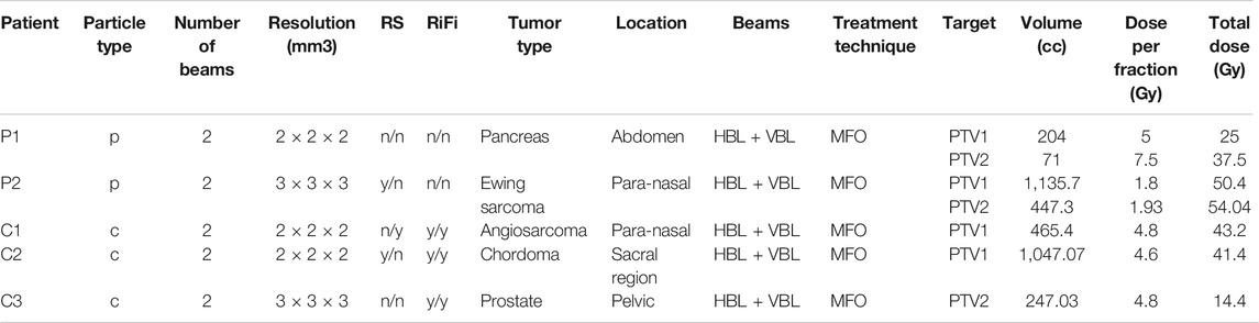
TABLE 1. Description of the clinical treatment plans verified with IDEAL. The columns RS and RiFi indicate the presence (y)/absence (n) of range shifter and ripple filters for each of the 2 beams used for each treatment. In the column Beams, HBL and VBL indicate usage of Horizontal and Vertical Beam Lines.
The IDEAL and TPS doses were also imported into VeriSoft version 7.2 (PTW, Freiburg, Germany) for computation of the gamma index in 3D. Gamma analysis was performed considering 3%/3mm and 3%/2 mm parameters, using dose difference normalized to the maximum dose and restricted to voxels having a dose larger than 10% of the maximum dose. Simulation times were also recorded.
Results
IDEAL Installation, Configuration and Acceptance
IDEAL was set-up on a cluster made of 1 submit node and 2 computing nodes of 24 physical cores each (48 cores in total). During acceptance, more than 60 tests were successfully conducted, on the functionalities, performances and accuracy of the system. The most relevant IDEAL configuration parameters were presented earlier and the selected settings for the implementation at MedAustron are briefly listed here: the same scoring resolution as the input TPS dose files was used and the dose outside the external ROI was removed. The CT protocol was automatically selected based on the SeriesDescription DICOM tag and the density tolerance was set to 0.01 g cm−3. A full geometrical description of the nozzle was provided for each beam line, together with beam models (source description file) for proton and carbon ion beams. The options dose to water, effective dose using a 1.1 RBE factor (for protons only) and plan dose were selected. The default Ntop (100) and p (50%) values were used. Dose scaling factors were defined during commissioning and configured. The GATE-RTion recommended proton and carbon ion physics-builder were used [15], namely QGSP_BIC_HP_EMZ and Shielding_EMZ. Cut, tracking cut and step-limiter values were set as presented in Table 2, following recommendations from the literature [5, 35], as a compromise between speed and accuracy. Further relevant details on the CT calibration and beam modeling details are provided in the following sections.
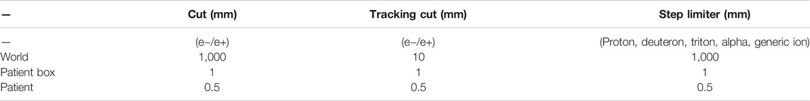
TABLE 2. GATE-RTion/Geant4 physics settings as configured in the IDEAL implementation used at MedAustron.
Commissioning Results
Beam Modeling Accuracy in 1D/2D
Beam ranges for protons and carbon ions simulated using GATE-RTion/IDEAL agreed very well with measured ranges in water with differences of less than 0.2 mm. Bragg peak width estimated at the 80% dose level were within 0.3 mm. Simulated beam sizes in air agreed nicely with measured data, with maximum deviation of less than 0.3 mm (in FWHM) at all measured positions in the beam path from nozzle exit until 20 cm after the treatment isocenter. At isocenter deviations were even lower, with maximum deviations of 0.2 mm. Overall agreement in range and beam optics were found to be close to the measurement uncertainties.
Beam Modeling Validation in 3D
In total for 3D validation, more than 34 proton treatment plans and 4.000 measurement points were evaluated. For carbon ions, the 4 key reference plans and more than 565 measurement points were considered. Scaling factors of 0.97 and 1.03 were applied to the proton and carbon ion beam models based on the review of the four reference boxes. The need for scaling factors may be due to a combination of dosimetric uncertainties and nuclear model uncertainties. All results presented in this section consider these two scaling factors. The overview of all 3D commissioning results is summarized in Table 3. The lower agreement considering the 3% dose difference criteria for carbon ions, as compared to protons, can be understood when looking at the results for the reference boxes in Table 4. One can see a dose output variation with energy as a function of the measurement depth for carbon ions, with an under-estimation of the dose in average of −2.1% for the deep seated box10, while the shallow box6 presents an overestimation of the dose by 0.8%. Overall, for both protons and carbon ions, the use of range shifter and different air gaps (ISD0 and ISD50) did not indicate any systematic deviation in the beam modeling results. The results presented are within clinical tolerances. The evaluation of the SOBP for the Box8 for both protons and carbon ions is illustrated in Figure 3.
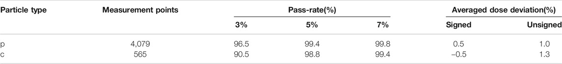
TABLE 3. 3D validation overview for protons and carbon ions in terms of pass-rates (considering dose difference criteria of 3%, 5% and 7%) and average dose deviations.
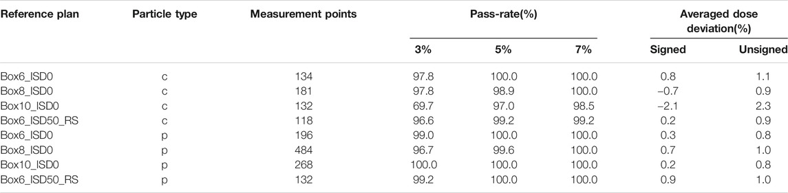
TABLE 4. 3D validation results for the reference boxes in terms of pass-rates (considering dose difference criteria of 3%, 5% and 7%) and average dose deviations.
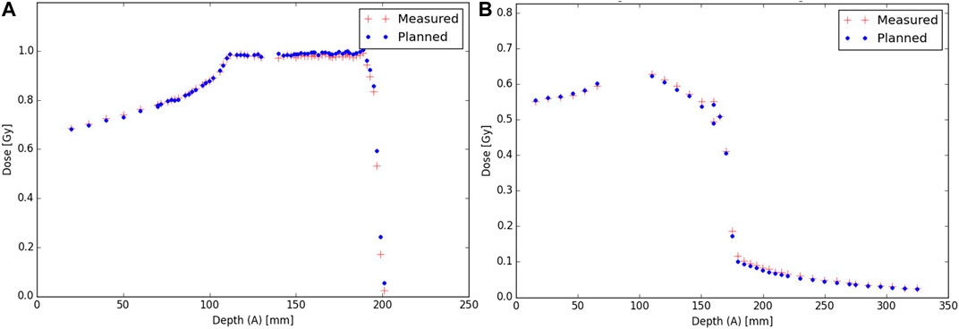
FIGURE 3. Evaluation of IDEAL Box8 for protons (A) and carbon ions (B) against measurements.
CT Calibration and Validation
The differences between the measured WET and each of the two simulated WET (using TPS and GATE-RTion/IDEAL) as a function of the tissue density is presented in Figure 4. For densities between 0.93 and 1.08 g cm−3, IDEAL overestimates the WET up to 3.8%. The WET calculated in the TPS presented a 1.2% better agreement with the measured WET in average. For low and high density materials, this tendency is not observed. A larger difference was found for both tissue groups with a maximum difference of 11% (bones/TPS) and 8.7% (bones/IDEAL). A difference up to 9.5% and 8.7% was found for lung/TPS and lung/IDEAL, respectively.
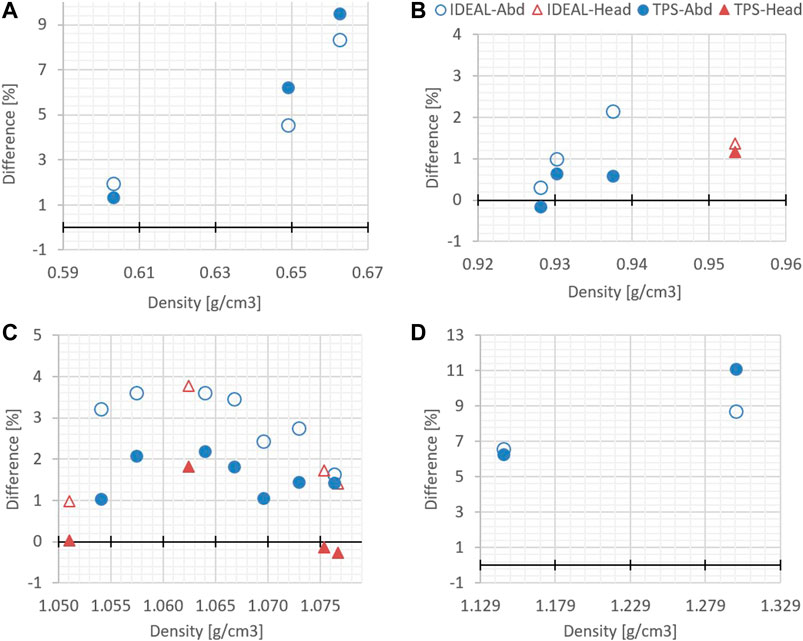
FIGURE 4. Differences between simulated WET (TPS and GATE-RTion/IDEAL) and measured WET, as a function of the tissue density. (A) corresponds to the lung region, (B) and (C) to the soft tissues regions and (D) to the bone region.
Evaluation of Clinical Cases With IDEAL
The evaluation of the 5 clinical treatment plans is summarized in Table 5. Gamma pass rate was higher than 97% for all plans considering the 3%/3 mm gamma parameters. Considering the 3%/2 mm gamma parameters, pass rate was higher than 95% for 3 patients and only slightly lower for P2 and C1. With respect to PTVs and OARs, mean doses and near maximum doses (D2%) parameter were in excellent agreement, within a few tenths of Gy. The near minimum doses (D98%) to the PTVs were also in excellent agreement for most plans, except for P2 which presented differences of 1.3 and 2 Gy for PTV2 and PTV1, respectively. This can be explained by the fact that a non-negligible part of the PTV overlaps with the lung, where the dose uncertainty is larger. An illustration of dose differences and dose profiles in that patient are presented in Figure 5. With respect to patient C1, differences were mostly related to the air cavities and the interface with dense bone. As the TPS features a pencil beam algorithm, one can expect MC to better perform in such a case. This fact is illustrated in Figure 6, where large differences in dose were observed in an air cavity, followed by a large range difference of up to 4 mm (yellow dose profile, Figure 6). In contrast, not going through any air cavity depicts an excellent agreement between the two dose engines (blue dose profile, Figure 6). To complete the evaluation, patient P1, for which gamma analysis was larger than 99% is presented in Figure 7. Dose differences within the target and plateau region were low. However, differences occur around the target, due to range differences between GATE-RTion/IDEAL and the TPS, where the horizontal and the vertical beams stop (Figure 7, bottom right). Agreement in terms of DVH was excellent (Figure 7, top right). Simulation times were varying significantly between protons and carbon ions and are discussed in the next section.
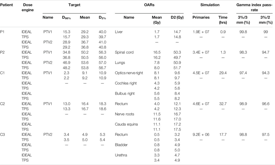
TABLE 5. Comparison of IDEAL simulations with TPS. Key clinical quantities for the target volumes (D98%, Mean dose, D2%) and organs at risks (Mean dose, D2%) are considered, as well as simulation times and gamma index pass-rates.
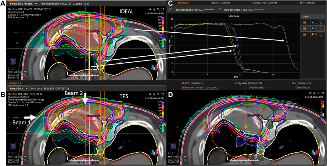
FIGURE 5. P2 evaluation. (A): 2D IDEAL dose distribution in a CT slice (transversal view), (B): 2D TPS dose distribution in a CT slice (transversal view), (C): 1D dose profiles extracted from the 2D IDEAL and TPS dose distributions presented on the (A,B) (full line = IDEAL, dotted line = TPS), (D): 2D dose difference in a CT slice extracted from the 2D IDEAL and TPS dose distributions presented on the (A,B) (IDEAL—TPS). Beam directions are represented on the (B) picture. On the (A) blue yellow and green lines represent the dose profiles presented on the (C).
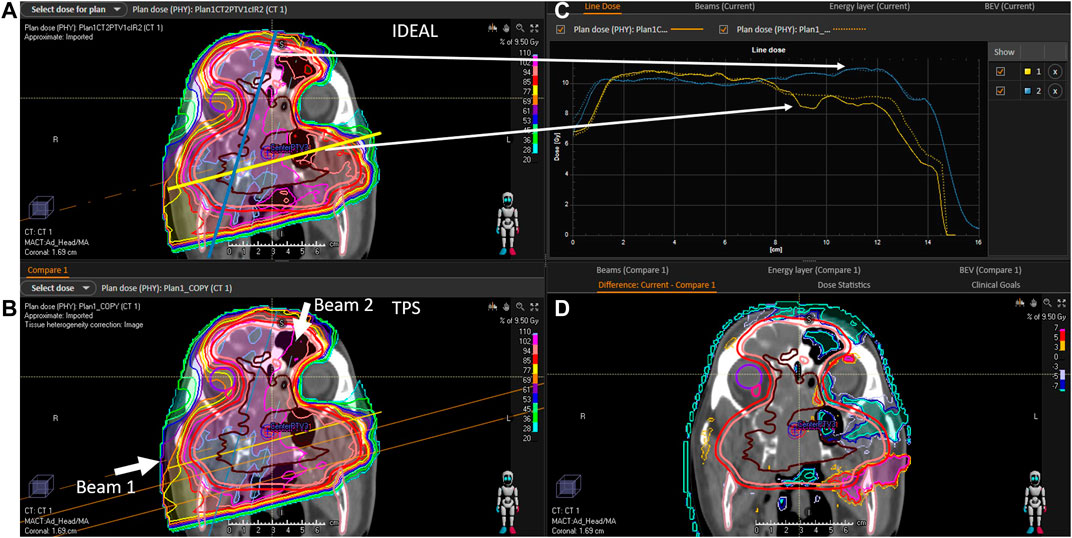
FIGURE 6. C1 evaluation (A): 2D IDEAL dose distribution in a CT slice (coronal view), (B): 2D TPS dose distribution in a CT slice (coronal view), (C): 1D dose profiles extracted from the 2D IDEAL and TPS dose distributions presented on the (A,B) (full line = IDEAL, dotted line = TPS), (D): 2D dose difference in a CT slice extracted from the 2D IDEAL and TPS dose distributions presented on the (A,B) (IDEAL—TPS). Beam directions are represented on the (B) picture. On the (A) blue and yellow lines represent the dose profiles presented on the (C).
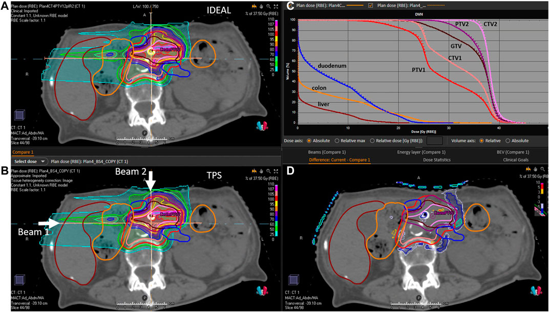
FIGURE 7. P1 evaluation. (A): 2D IDEAL dose distribution in a CT slice (transversal view), (B): 2D TPS dose distribution in a CT slice (transversal view), (C): 1D dose volume histograms extracted from the 3D IDEAL and TPS dose distributions (full line = IDEAL, dotted line = TPS), (D): 2D dose difference in a CT slice extracted from the 2D IDEAL and TPS dose distributions presented on the (A,B) (IDEAL—TPS). Beam directions are represented on the (B) picture.
Discussion
Simulation times were presented in Table 5. Patient P2 and C2, both have a tumor volume slightly larger than 1 L. While the proton simulation result was obtained in 1.3 h, the carbon ion simulation took 32.7 h using the current cluster capacity of 48 cores. The reasons for larger computation times with carbon ions are partly due to the production and tracking of nuclear secondaries, which stop after the primary carbon ion range and produce the dose tail after the carbon ion Bragg peak. In addition, simulation speed may be significantly influenced by the nuclear models selected in Geant4. The QMD model selected in this study is assumed to be the most accurate, however it was shown that its computation speed can be at least a factor 2 to 3 slower, than other standard models such as BIC [36]. For daily clinical use, simulation times of the order of 1–2 h maximum are desirable. In the context of this study, we recomputed patient C2, using a scoring grid of 3 mm (which for the pelvic region is clinically acceptable) and considered a statistical uncertainty of 2%, which reduced the computation time to 4.3 h. The gamma pass rates at 3%/3mm and 2%/2 mm were 97.8 and 94.4%, respectively, which is logically lower than the 98.8 and 96.6% pass rates from the reference simulation (with 2 mm scoring grid and 1% statistical uncertainty). Increasing the gamma criteria (for the 3 mm resolution and 2% uncertainty simulation) to 4%/3 mm and 4%/2 mm provided gamma pass rates of 99.1 and 97.5%, respectively. It seems therefore clinically acceptable to adapt the dose grid and simulation uncertainty requirement, if needed, in order to reduce computation time to clinically acceptable values. Increasing the cluster capacity by a factor 2, would bring the computation time down to the order of 2 h in such a case. In addition and as mentioned earlier, using alternative and faster nuclear models such as BIC could be an option, but commissioning should be repeated.
The IDC concept was already recommended and implemented as a routine QA tool in conventional radiotherapy in the last century. Unfortunately, the traditional empirical dose calculation models were of very limited applicability for advanced treatment techniques, such as Intensity Modulated Radiation Therapy (IMRT). Experimental methods were therefore implemented for PSQA, thus substituting IDC for complex treatment techniques. As the number of patients treated with advanced radiotherapy techniques steadily increased over the years, experimental PSQA resulted in a significantly increased workload. In 2010, ESTRO published a booklet on “Independent Dose Calculations Concepts and Models” [37]. At that time, one key limitation of both types of QA (experimental and IDC), was that verification was performed in a homogeneous phantom and not in the patient geometry. Nevertheless, it was already suggested that IDC could be used to replace experimental PSQA [38, 39]. Development of dose calculation algorithms over the years made IDC the only possibility to perform QA in the patient geometry. Nowadays, it seems that the radiation therapy community in general (including both conventional and LIBT), is moving back to the roots of PSQA using IDC, rather than experimental PSQA [40]. In the framework of the Imaging and Radiation Oncology Core (IROC) [41], it was demonstrated that IDC was 12 times more sensitive at detecting treatment failures for IMRT than experimental PSQA. The commissioning of the first commercial IDC system for CyberKnife and based on a MC algorithm was reported in [42]. The main conclusion stated that this IDC system will replace all routine experimental PSQA. One motivation from the authors is related to the complexity of the measurements and as for the previous study, a lack of sensitivity of the experimental PSQA, which is limited to the beam delivery and therefore could be replaced by an appropriate machine QA program. For protons, the first commercial and MC-based IDC system, called myQA iON (IBA-dosimetry, Schwarzenbruck, Germany), was recently commissioned and implemented clinically at the MedAustron ion therapy facility. Experimental PSQA was reduced by 25% and it will increase step-wise up to 50% on average by the end of 2021.
The substitution of experimental PSQA by IDC allows for further improvements of the QA process, for instance by combining IDC with treatment log-files. The use of treatment log files allows in theory verifying machine delivery parameters for any treatment fraction, thus overcoming the capabilities of experimental PSQA, which is limited to a single fraction delivered to a QA phantom prior treatment. Integrating log-files as inputs to an IDC system was shown to be much more sensitive in detecting proton delivery errors, than experimental PSQA. Indeed, out of 21 error scenarios tested, 11 were detected by IDC and only 1 by PSQA [9]. Log-file-based QA is suggested as a potential improvement to bridge the gap between machine QA, PSQA and daily patient treatment [7, 42]. Artifical Intelligence may also play a role in future to support, for instance, the prediction of possible PSQA failures [43].
In the context of adaptive radiotherapy, the aim is to shorten the cycle between image generation, contouring, plan adaptation and treatment. Hence, it is very important to be able to quickly recompute the dose into the daily patient anatomy. The development of fast IDC systems and further optimized QA is a necessity for such applications. IDC tolerance levels should be related to Tumor Control Probability (TCP) and Normal Tissue Complication Probability (NTCP) [37]. A first attempt in this direction was provided in [11], but with another initial purpose in the framework of Model-Based approaches, to confirm the decision-making process for patient selection, when NTCP models are used as a basis. If NTCP models are not available (or not calibrated for the clinics), the review of DVHs and clinical goals is actually a practical alternative to evaluate IDC-based PSQA outcome in a more clinically relevant manner.
In the context of LIBT, including particles others than protons (e.g. carbon ions), no commercial system is currently available. Currently, the only commercial TPS available is RayStation (RaySearch Laboratories, Stockholm, Sweden). For carbon ions, the pencil beam algorithm developments of RayStation were largely based on pre-calculations performed using the FLUKA MC code. In this respect, IDEAL represents an interesting solution for MC-based IDC, as it is based on GATE-RTion and the Geant4 [15, 44, 45] physics models. For the purpose of replacing experimental PSQA by IDC-based PSQA, evaluating the physical dose distribution in the patient may be sufficient. For protons, a fixed 1.1 RBE value may be used. However, variable proton RBE values were suggested, as there is evidence of increased RBE towards the end of the Bragg peak [46]. For carbon ions, several RBE models are available, but the uncertainties of these models are rather large [47, 48]. The implementation of various RBE models for the purpose of proton and carbon ion IDC may support research projects. For the clinical purpose of independently evaluating the TPS dose computation, very similar RBE models should be implemented in the IDC tool and in the TPS, otherwise large discrepancies between the two dose engines would be observed due to the RBE models uncertainty, thus making the clinical evaluation very difficult.
In this work, the GATE-RTion/IDEAL software version 1.0 was presented and the clinical implementation methodology was described in detail. IDEAL was applied retrospectively for 5 clinical treatments and was found to successfully perform IDC in the field of LIBT for scanned proton and carbon ion beams. Thanks to its DICOM-in/DICOM-out design fashion, IDEAL was easily compatible with state-of-the-art technology, thus allowing for dose review and comparison in different medical Software. IDEAL is provided open-source and is maintained by the OpenGATE community. It will therefore benefit of further upgrades tailored by medical and research needs in future.
Data Availability Statement
The raw data supporting the conclusion of this article will be made available by the authors, without undue reservation.
Author Contributions
LG is the lead author. He coordinated the project work and was in charge of the carbon ion commissioning and clinical examples. DB is the second lead author in equal contribution with LG, as he was the main developer of IDEAL. HF was in charge of acceptance testing and beam modelling. MB-F was in charge of the commissioning the HU curves. LS was in charge of proton commissioning. DG was the project coordinator from MUW. GK was the project coordinator from ACMIT. MS was the project coordinator from MedAustron.
Funding
The financial support from ACMIT Gmbh, Medical University of Vienna and MedAustron is gratefully acknowledged. The competence center ACMIT is funded within the scope of the COMET program (Competence Centers for Excellent Technologies) by Austrian ministries BMK and BMDW, and by the governments of Lower Austria and Tyrol. The competence center program COMET is managed by the Austrian Funding Agency FFG.
Conflict of Interest
DB and GK were employed by the company ACMIT Gmbh.
The remaining authors declare that the research was conducted in the absence of any commercial or financial relationships that could be construed as a potential conflict of interest.
Publisher’s Note
All claims expressed in this article are solely those of the authors and do not necessarily represent those of their affiliated organizations, or those of the publisher, the editors and the reviewers. Any product that may be evaluated in this article, or claim that may be made by its manufacturer, is not guaranteed or endorsed by the publisher.
Acknowledgments
Joanna Gora and Antonio Carlino from MedAustron are gratefully acknowledged for providing support in IDEAL CT calibration validation and dosimetric commissioning, respectively. Alessio Elia is gratefully acknowledged for fruitful discussions on GATE Monte Carlo simulations and proton IDC. Ruben Gonzalo Gleyzes is deeply acknowledged for his continuous support on the development of the TEDD toolkit.
Footnotes
1https://www.ptcog.ch/index.php/facilities-in-operation.
2https://github.com/OpenGATE/IDEAL.
3https://pyidc.readthedocs.io/en/1.0.
4https://research.cs.wisc.edu/htcondor/htc.html.
References
1. Stock M, Georg D, Ableitinger A, Zechner A, Utz A, Mumot M, et al. The Technological Basis for Adaptive Ion Beam Therapy at MedAustron: Status and Outlook. Z für Medizinische Physik (2018) 28(3):196–210. doi:10.1016/j.zemedi.2017.09.007
2. Ortiz López P, Cosset JM, Dunscombe P, Holmberg O, Rosenwald JC, Pinillos Ashton L, et al. ICRP Publication 112. A Report of Preventing Accidental Exposures from New External Beam Radiation Therapy Technologies. Ann ICRP 112 (2009) 39(4):1–86. doi:10.1016/j.icrp.2010.02.002
3. Mackin D, Li Y, Taylor MB, Kerr M, Holmes C, Sahoo N, et al. Improving Spot-Scanning Proton Therapy Patient Specific Quality Assurance with HPlusQA, a Second-Check Dose Calculation Engine. Med Phys (2013) 40(12):121708. doi:10.1118/1.4828775 Available from: http://www.ncbi.nlm.nih.gov/pubmed/24320494.
4. Fracchiolla F, Lorentini S, Widesott L, Schwarz M. Characterization and Validation of a Monte Carlo Code for Independent Dose Calculation in Proton Therapy Treatments with Pencil Beam Scanning. Phys Med Biol (2015) 60(21):8601–19. doi:10.1088/0031-9155/60/21/8601
5. Winterhalter C, Taylor M, Boersma D, Elia A, Guatelli S, Mackay R, et al. Evaluation of GATE-RTion (GATE/Geant4) Monte Carlo Simulation Settings for Proton Pencil Beam Scanning Quality Assurance. Med Phys (2020) 47(11):5817–5828. doi:10.1002/mp.14481
6. Aitkenhead A, Sitch P, Jenny R, Winterhalter C, Patel I, Ranald M. Automated Monte-Carlo Re-calculation of Proton Therapy Plans Using Geant4/Gate: Implementation and Comparison to Plan-specific Quality Assurance Measurements. Br J Radiol (2020) 93(1114):20200228. doi:10.1259/bjr.20200228
7. Johnson JE, Beltran C, Wan Chan Tseung H, Mundy DW, Kruse JJ, Whitaker TJ, et al. Highly Efficient and Sensitive Patient-specific Quality Assurance for Spot-Scanned Proton Therapy. PLoS One (2019) 14(2):e0212412. doi:10.1371/journal.pone.0212412
8. Meier G, Besson R, Nanz A, Safai S, Lomax AJ. Independent Dose Calculations for Commissioning, Quality Assurance and Dose Reconstruction of PBS Proton Therapy. Phys Med Biol (2015) 60(7):2819–36. Available from. doi:10.1088/0031-9155/60/7/2819
9. Matter M, Nenoff L, Meier G, Weber DC, Lomax AJ, Albertini F. Alternatives to Patient Specific Verification Measurements in Proton Therapy: a Comparative Experimental Study with Intentional Errors. Phys Med Biol (2018) 63(20):205014. doi:10.1088/1361-6560/aae2f4
10. Guterres Marmitt G, Pin A, Ng Wei Siang K, Janssens G, Souris K, Cohilis M, et al. Platform for Automatic Patient Quality Assurance via Monte Carlo Simulations in Proton Therapy. Physica Med (2020) 70 (September):49–57. Available from. doi:10.1016/j.ejmp.2019.12.018
11. Meijers A, Guterres Marmitt G, Ng Wei Siang K, van der Schaaf A, Knopf AC, Langendijk JA, et al. Feasibility of Patient Specific Quality Assurance for Proton Therapy Based on Independent Dose Calculation and Predicted Outcomes. Radiother Oncol (2020) 150:136–41. Available from:. doi:10.1016/j.radonc.2020.06.027
12. Mein S, Choi K, Kopp B, Tessonnier T, Bauer J, Ferrari A, et al. Fast Robust Dose Calculation on GPU for High-Precision 1H, 4He, 12C and 16O Ion Therapy: the FRoG Platform. Sci Rep (2018) 8(1):1–12. doi:10.1038/s41598-018-33194-4
13. Schiavi A, Senzacqua M, Pioli S, Mairani A, Magro G, Molinelli S, et al. Fred: A GPU-Accelerated Fast-Monte Carlo Code for Rapid Treatment Plan Recalculation in Ion Beam Therapy. Phys Med Biol (2017) 62(18):7482–504. doi:10.1088/1361-6560/aa8134
14. Kozłowska WS, Böhlen TT, Cuccagna C, Ferrari A, Fracchiolla F, Magro G, et al. FLUKA Particle Therapy Tool for Monte Carlo Independent Calculation of Scanned Proton and Carbon Ion Beam Therapy. Phys Med Biol (2019) 64(7):075012. doi:10.1088/1361-6560/ab02cb
15. Grevillot L, Boersma DJ, Fuchs H, Aitkenhead A, Elia A, Bolsa M, et al. Technical Note: GATE‐RTion: a GATE/Geant4 Release for Clinical Applications in Scanned Ion Beam Therapy. Med Phys (2020) 47(8):3675–81. doi:10.1002/mp.14242
16. Elia A, Resch AF, Carlino A, Böhlen TT, Fuchs H, Palmans H, et al. A GATE/Geant4 Beam Model for the MedAustron Non-isocentric Proton Treatment Plans Quality Assurance. Physica Med (2020) 71:115–23. Available from. doi:10.1016/j.ejmp.2020.02.006–
17. Grevillot L, Boersma D, Gleyzes RG, Scheuchenpflug L, Carlino A, Elia A, et al. OC-0217: Commissioning of IDEAL/GATE-RTion for Proton and Carbon Ion Independent Dose Calculation (IDC). In: ESTRO 2020 (2020). [Internet]. Available from: https://www.estro.org/Congresses/ESTRO-2020/197/profferedpapers11-dosecalculationforadvancedtechni/160/commissioningofideal-gate-rtionforprotonandcarboni
18. Fuchs H, Vatnitsky S, Stock M, Georg D, Grevillot L. Evaluation of GATE/Geant4 Multiple Coulomb Scattering Algorithms for a 160 MeV Proton Beam. Nucl Instr Methods Phys Res Sect B Beam Interact Mater Atoms (2017) 410:122–126. doi:10.1016/j.nimb.2017.08.006
19. Grevillot L, Stock M, Vatnitsky S Evaluation of Beam Delivery and Ripple Filter Design for Non-isocentric Proton and Carbon Ion Therapy. Phys Med Biol (2015) 60(20):7985–8005. Available from: http://www.ncbi.nlm.nih.gov/pubmed/26418366. doi:10.1088/0031-9155/60/20/7985
20. Böhlen TT, Cerutti F, Dosanjh M, Ferrari A, Gudowska I, Mairani A, et al. Benchmarking Nuclear Models of FLUKA and GEANT4 for Carbon Ion Therapy. Phys Med Biol (2010) 55(19):5833–47. Available from. doi:10.1088/0031-9155/55/19/014
21. Resch A, Lackner N, Niessen T, Engdahl S, Elia A, Boersma D, et al. Impact of Beamline-specific Particle Energy Spectra on Clinical Plans in Carbon Ion Beam Therapy. In: ESTRO Conference, 39 (2020). p. OC-0577.
22. Grevillot L, Bertrand D, Dessy F, Freud N, Sarrut D GATE as a GEANT4-Based Monte Carlo Platform for the Evaluation of Proton Pencil Beam Scanning Treatment Plans. Phys Med Biol (2012) 57(13):4223–44. Available from: http://www.ncbi.nlm.nih.gov/pubmed/22684098. doi:10.1088/0031-9155/57/13/4223
23. Schneider W, Bortfeld T, Schlegel W. Correlation between CT Numbers and Tissue Parameters Needed for Monte Carlo Simulations of Clinical Dose Distributions. Phys Med Biol (2000) 45(2):459–78. doi:10.1088/0031-9155/45/2/314
24. Grevillot L, Bertrand D, Dessy F, Freud N, Sarrut D. A Monte Carlo Pencil Beam Scanning Model for Proton Treatment Plan Simulation Using GATE/GEANT4. Phys Med Biol (2011) 56(16):5203–19. doi:10.1088/0031-9155/56/16/008 Available from: http://www.ncbi.nlm.nih.gov/pubmed/21791731.
25. Deschler T, Arbor N, Carbillet F, Nourreddine A. Dose Calculations in Heterogeneous Volumes with the GATE Monte Carlo Software for Radiological protection. Radioprotection (2019) 54(2):125–32. doi:10.1051/radiopro/2019014
26. Paganetti H. Dose to Water versus Dose to Medium in Proton Beam Therapy. Phys Med Biol (2009) 54(14):4399–421. Available from:. doi:10.1088/0031-9155/54/14/004
27. Fuchs H, Elia A, Resch AF, Kuess P, Lühr A, Vidal M, et al. Computer-assisted Beam Modeling for Particle Therapy. Med Phys (2020) 48(2):841–51. doi:10.1002/mp.14647
28. Grevillot L, Osorio Moreno J, Letellier V, Dreindl R, Elia A, Fuchs H, et al. Clinical Implementation and Commissioning of the MedAustron Particle Therapy Accelerator for Non‐isocentric Scanned Proton Beam Treatments. Med Phys (2019) 1–13. doi:10.1002/mp.13928
29. Carlino A, Böhlen T, Vatnitsky S, Grevillot L, Osorio J, Dreindl R, et al. Commissioning of Pencil Beam and Monte Carlo Dose Engines for Non-isocentric Treatments in Scanned Proton Beam Therapy. Phys Med Biol (2019) 64(17):17NT01. doi:10.1088/1361-6560/ab3557
30. Scheuchenpflug L “ Development of a Commissioning Tool for the Independent Dose Calculation Software IDEAL for the Patient Specific Quality Assurance at MedAustron. “Vienna: University of Vienna (2020). MASTER’S THESIS.
31. Góra J, Kragl G, Vatnitsky S, Böhlen TT, Teichmeister M, Stock M. Validation of the CT Number to Mass Density Conversion Curve for Proton Dose Calculation: Proton Range Measurements in Animal Tissues. In: ESTRO Conference 36. Vienna, Austria (2017).
32. White DR, Booz J, Griffith RV, Spokas JJ, Wilson IJ ICRU Report 44, the Composition of Body Tissues. [Internet]. Reports Int Comm Radiat Units Meas (1989). Available from: https://academic.oup.com/jicru/issue/16/1-2.
33. Das IJ, Paganetti H. Principles and Practice of Proton Beam Therapy. Colorado Springs: AAPM Monograph, 2015 Summer School (2015).
34. Zhu XR, Poenisch F, Li H, Zhang X, Sahoo N, Wu RY, et al. A Single-Field Integrated Boost Treatment Planning Technique for Spot Scanning Proton Therapy. Radiat Oncol (2014) 9(1):1–12. doi:10.1186/1748-717x-9-202
35. Grevillot L, Frisson T, Zahra N, Bertrand D, Stichelbaut F, Freud N, et al. Optimization of GEANT4 Settings for Proton Pencil Beam Scanning Simulations Using GATE. Nucl Instr Methods Phys Res Sect B: Beam Interact Mater Atoms (2010) 268(20):3295–305. doi:10.1016/j.nimb.2010.07.011
36. Bolst D, Cirrone GAP, Cuttone G, Folger G, Incerti S, Ivanchenko V, et al. Validation of Geant4 Fragmentation for Heavy Ion Therapy. [Internet]. Nucl Instr Methods Phys Res Sect A (2017) 869:68–75. doi:10.1016/j.nima.2017.06.046
37. Karlsson M, Ahnesjö A, Georg D, Nyholm T, Olofsson J. Independent Dose Calculations Concepts and Models. In: ESTRO Booklet N°10. Brussels: ESTRO (2010).
38. Georg D, Nyholm T, Olofsson J, Kjær-Kristoffersen F, Schnekenburger B, Winkler P, et al. Clinical Evaluation of Monitor Unit Software and the Application of Action Levels. Radiother Oncol (2007) 85(2):306–15. doi:10.1016/j.radonc.2007.04.035
39. Georg D, Stock M, Kroupa B, Olofsson J, Nyholm T, Ahnesjö A, et al. Patient-specific IMRT Verification Using Independent Fluence-Based Dose Calculation Software: Experimental Benchmarking and Initial Clinical Experience. Phys Med Biol (2007) 52(16):4981–92. doi:10.1088/0031-9155/52/16/018
40. Zhu TC, Stathakis S, Clark JR, Feng W, Georg D, Holmes SN, et al. Report of AAPM Task Group 219 on Independent Calculation-Based Dose/MU Verification for IMRT. Med Phy (2021) doi:10.1002/mp.15069
41. Kry SF, Glenn MC, Peterson CB, Branco D, Mehrens H, Steinmann A, et al. Independent Recalculation Outperforms Traditional Measurement‐based IMRT QA Methods in Detecting Unacceptable Plans. Med Phys (2019) 46(8):3700–8. doi:10.1002/mp.13638
42. Milder MTW, Alber M, Söhn M, Hoogeman MS. Commissioning and Clinical Implementation of the First Commercial Independent Monte Carlo 3D Dose Calculation to Replace CyberKnife M6 Patient‐specific QA Measurements. J Appl Clin Med Phys (2020) 21(11):304–11. doi:10.1002/acm2.13046
43. Valdes G, Adamson J, Cai J. Artificial Intelligence for Prediction of Measurement‐based Patient‐specific Quality Assurance Is Ready for Prime Time. Med Phys (2021) 48:2701–4. doi:10.1002/mp.14870
44. Jan S, Benoit D, Becheva E, Carlier T, Cassol F, Descourt P, et al. GATE V6: a Major Enhancement of the GATE Simulation Platform Enabling Modelling of CT and Radiotherapy. Phys Med Biol (2011) 56(4):881–901. Available from: http://iopscience.iop.org/article/10.1088/0031-9155/56/4/001/pdf. doi:10.1088/0031-9155/56/4/001
45. Allison J, Amako K, Apostolakis J, Arce P, Asai M, Aso T, et al. Recent Developments in GEANT4. Nucl Instr Methods Phys Res Sect A (2016) 835(July):186–225. Available from. doi:10.1016/j.nima.2016.06.125
46. Paganetti H, Blakely E, Carabe-Fernandez A, Carlson DJ, Das IJ, Dong L, et al. Report of the AAPM TG-256 on the Relative Biological Effectiveness of Proton Beams in Radiation Therapy. Med Phys (2019) 46(3):e53–e78. doi:10.1002/mp.13390
47. Schardt D, Elsässer T, Schulz-Ertner D. Heavy-ion Tumor Therapy: Physical and Radiobiological Benefits. Rev Mod Phys (2010) 82:383–425. doi:10.1103/revmodphys.82.383
Keywords: GATE, GEANT4, independent dose caculation, proton, carbon ion, light ion beam therapy, IDEAL, GATE-RTion
Citation: Grevillot L, Boersma DJ, Fuchs H, Bolsa-Ferruz M, Scheuchenpflug L, Georg D, Kronreif G and Stock M (2021) The GATE-RTion/IDEAL Independent Dose Calculation System for Light Ion Beam Therapy. Front. Phys. 9:704760. doi: 10.3389/fphy.2021.704760
Received: 03 May 2021; Accepted: 14 July 2021;
Published: 11 August 2021.
Edited by:
Miguel Antonio Cortés-Giraldo, Sevilla University, SpainReviewed by:
Daniel Sanchez-Parcerisa, Complutense University of Madrid, SpainStanislav Pospíšil, Czech Technical University in Prague, Czechia
Copyright © 2021 Grevillot, Boersma, Fuchs, Bolsa-Ferruz, Scheuchenpflug, Georg, Kronreif and Stock. This is an open-access article distributed under the terms of the Creative Commons Attribution License (CC BY). The use, distribution or reproduction in other forums is permitted, provided the original author(s) and the copyright owner(s) are credited and that the original publication in this journal is cited, in accordance with accepted academic practice. No use, distribution or reproduction is permitted which does not comply with these terms.
*Correspondence: L. Grevillot, loic.grevillot@medaustron.at
†These authors have contributed equally to this work and share first authorship