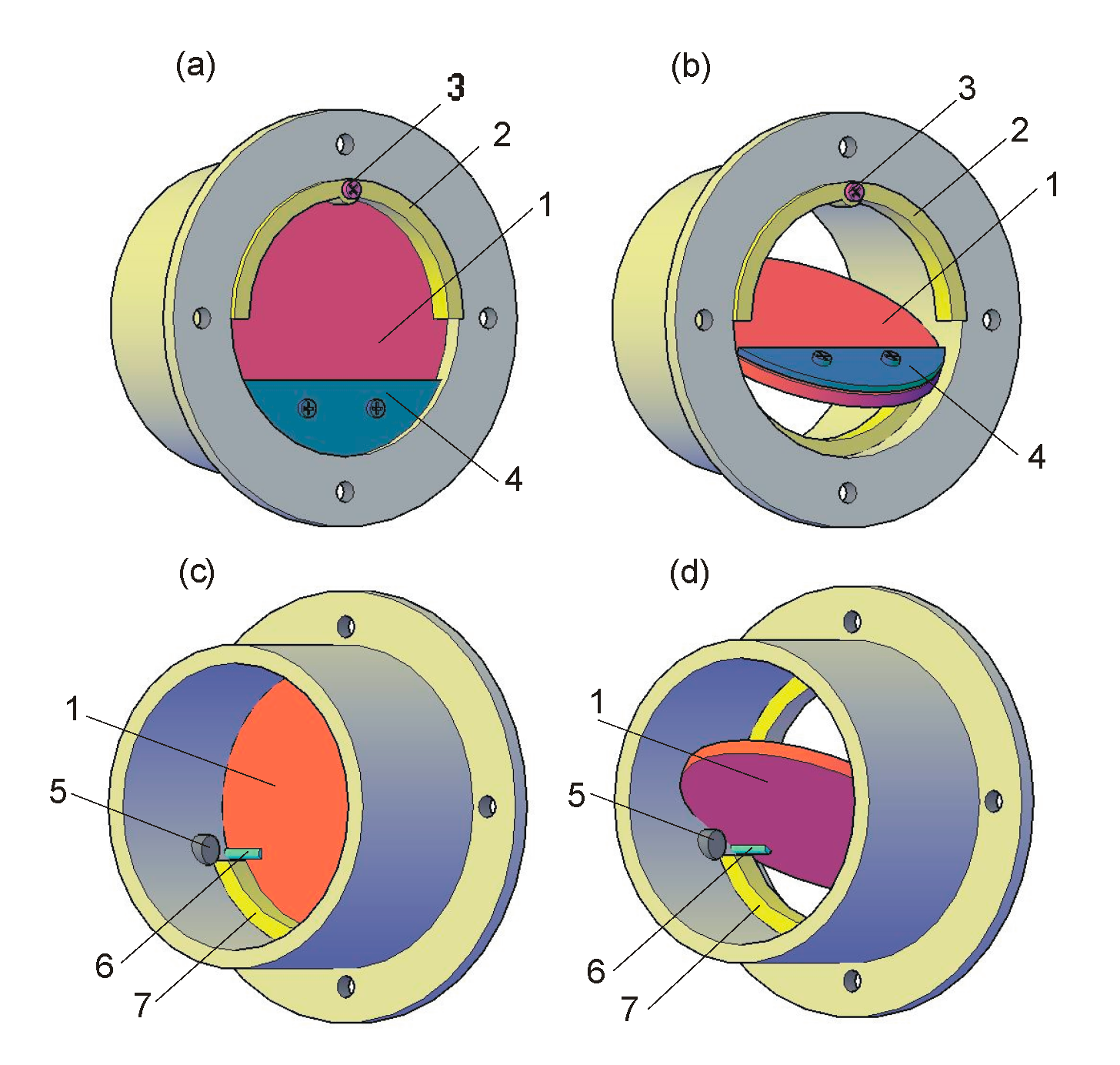
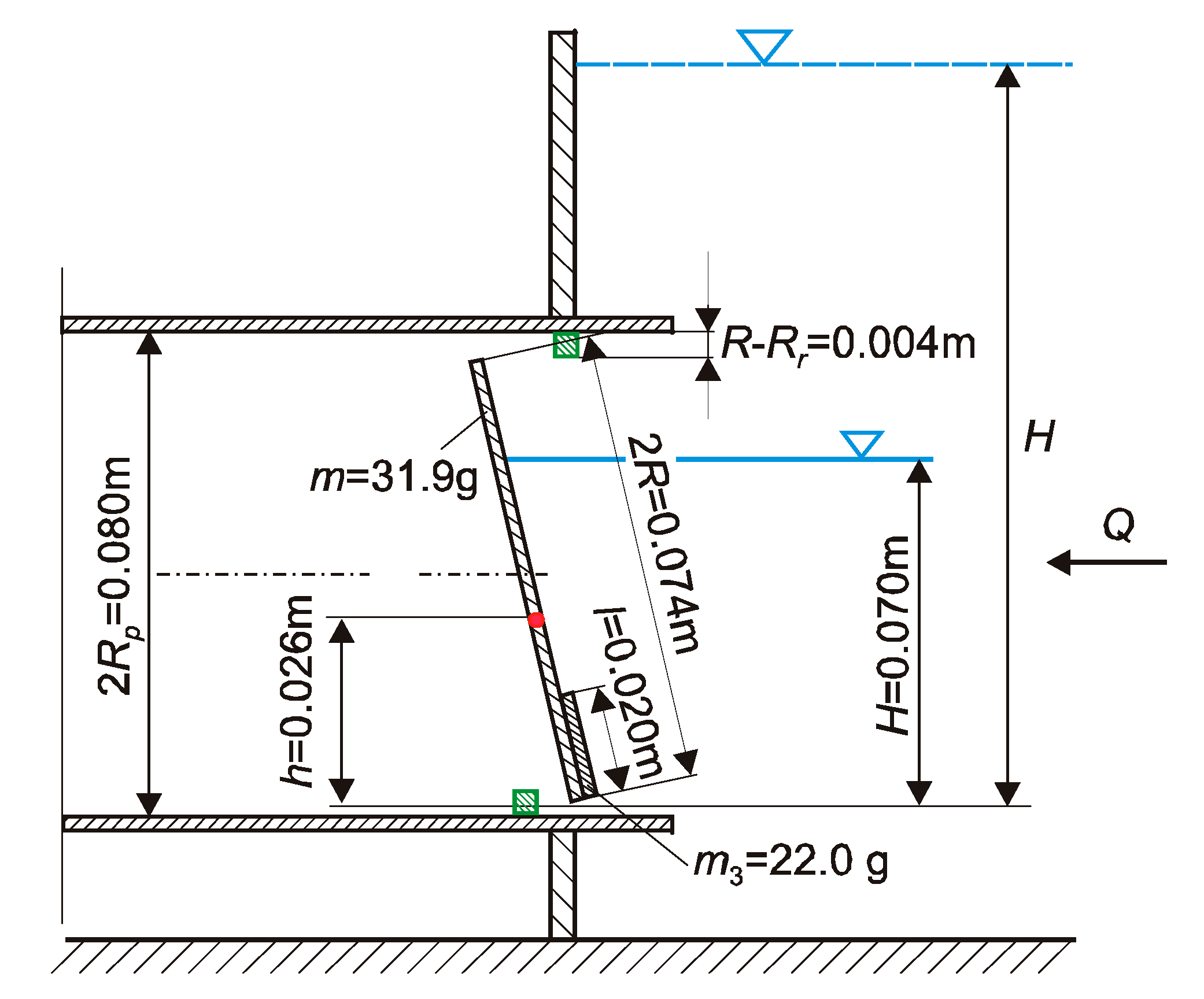
2. The Principle of Operation of the Circular Flap Gate Design
The upstream water level control device consists of a rotating, circular metal flap gate placed in a pipe and fixed on a horizontal axis of rotation (
Figure 1).
In the absence of water in the downstream side of the regulator, the circular flap gate opens when the opening moment caused by the hydrostatic force exerted on the flap gate surface above its axis of rotation exceeds the value of the closing moment caused by the hydrostatic force exerted on the flap gate surface below its axis of rotation. By adjusting the position of the circular flap gate’s axis of rotation h, it can open during both a free surface flow, when the water level is lower than the pipe diameter, and pressurized flow conditions. The angle of gate opening can be regulated with a flap stop mounted in a pipe (5 in
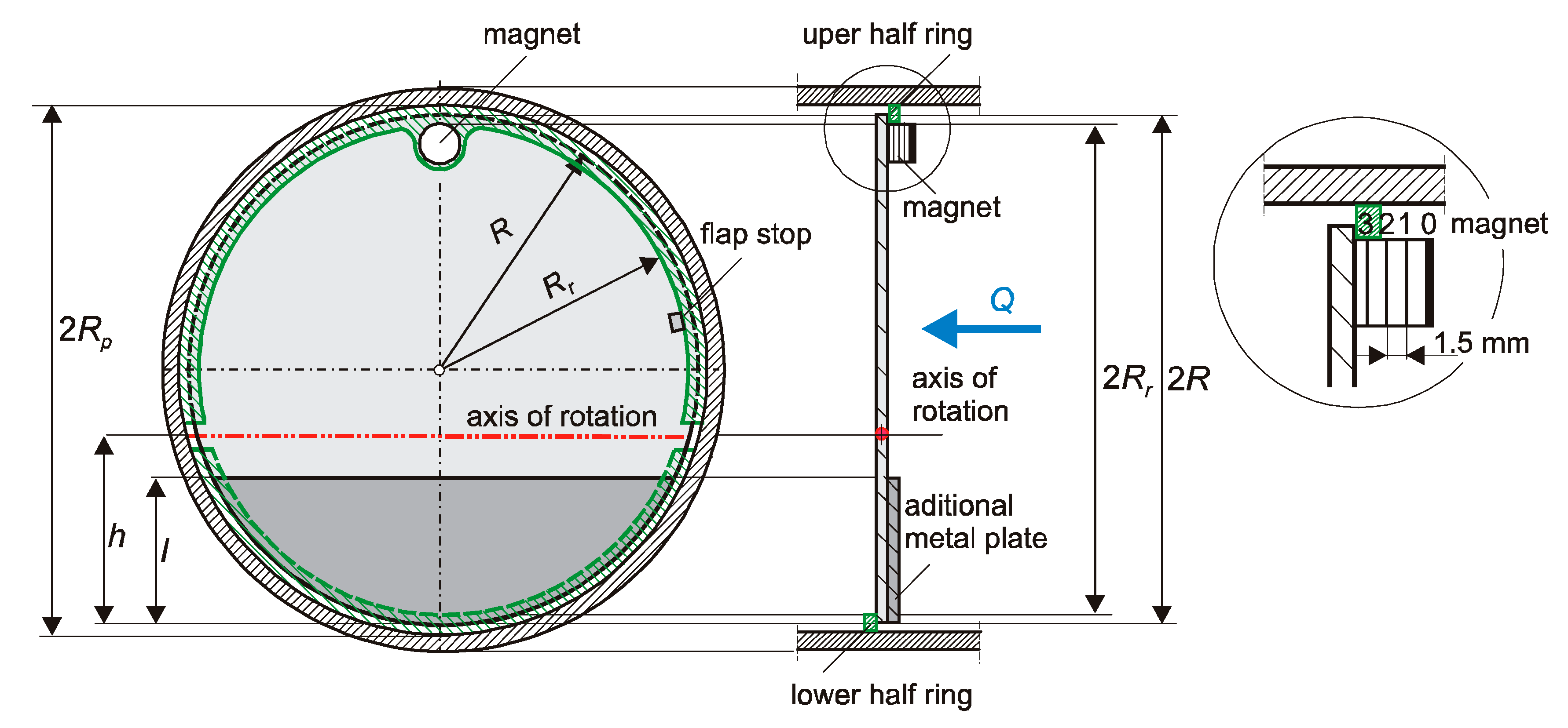
Figure 1). Since the axis of rotation of the circular flap gate lies below its center of mass, in order to allow the flap gate to automatically close, it is necessary to increase the weight of the bottom part of the flap gate. This was achieved by attaching an additional mass in the form of metal plates with a height of
l cut from a circular plate with a diameter equal to the diameter of the flap gate
2R (
Figure 2). To reduce the water flow between wall of the pipe and the flap gate, two half-rings were placed in the pipe on both sides of the flap gate.
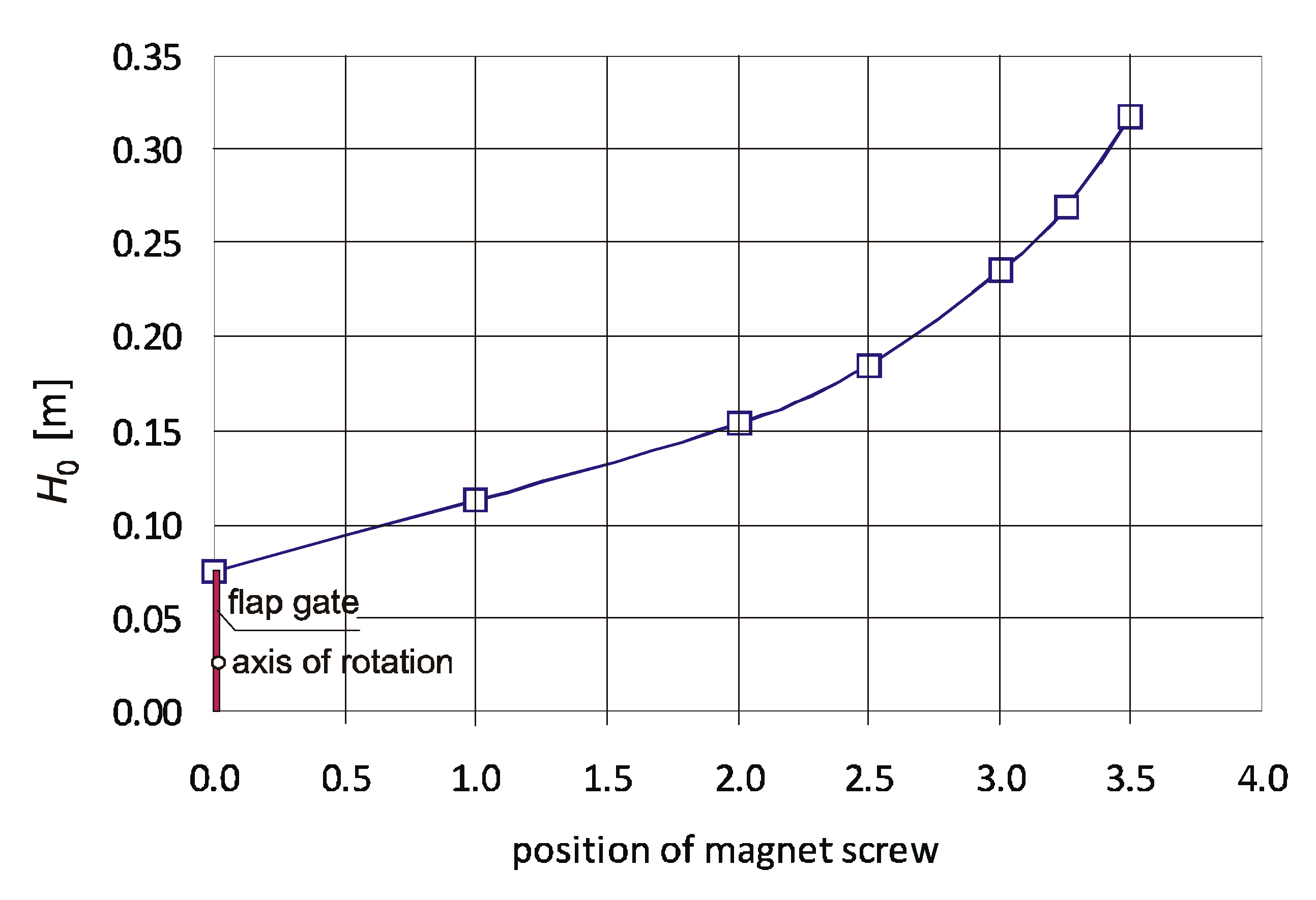
In order to smoothly adjust the closing moment, in the upper half-ring, a screw ended with a magnet is installed (
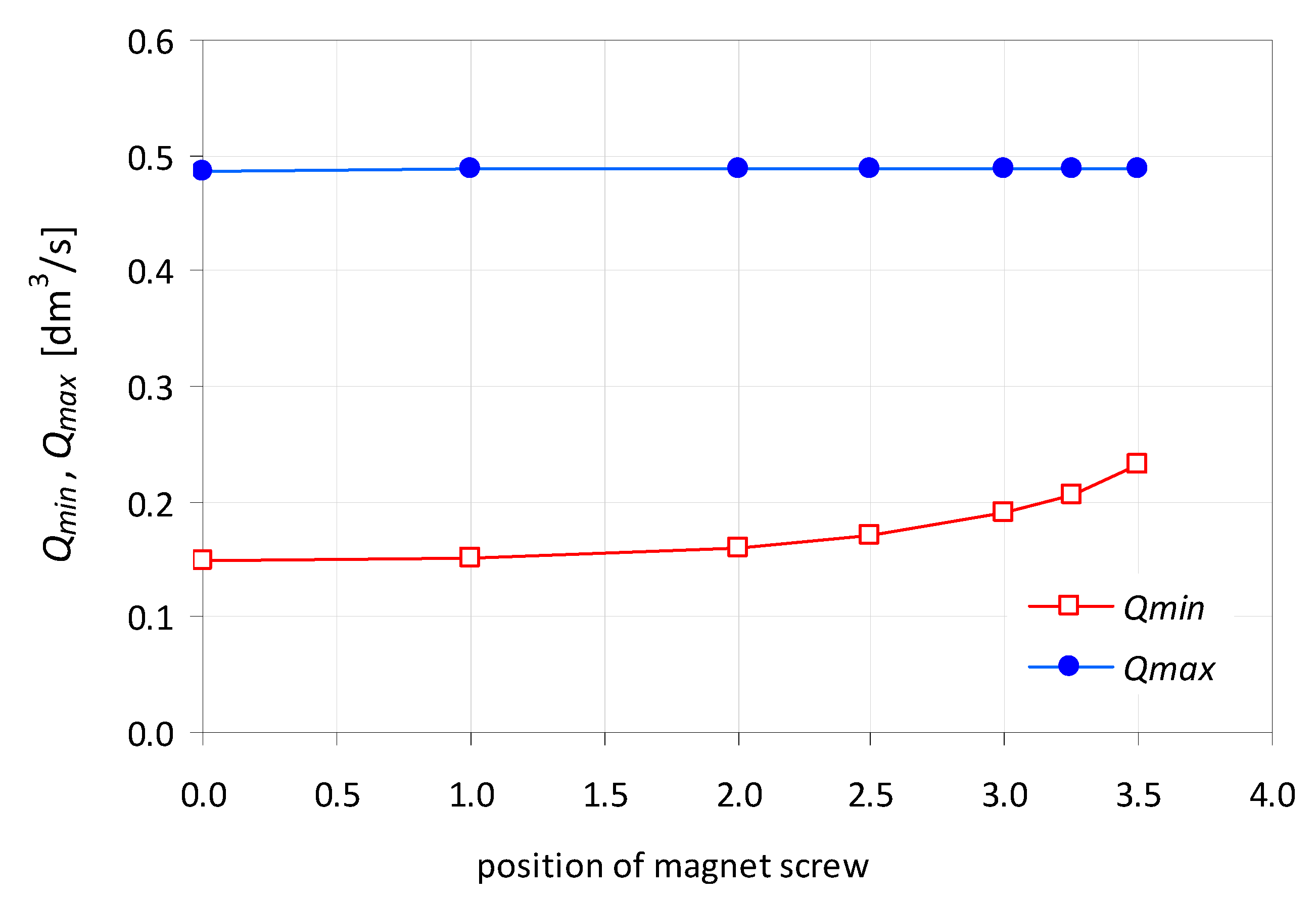
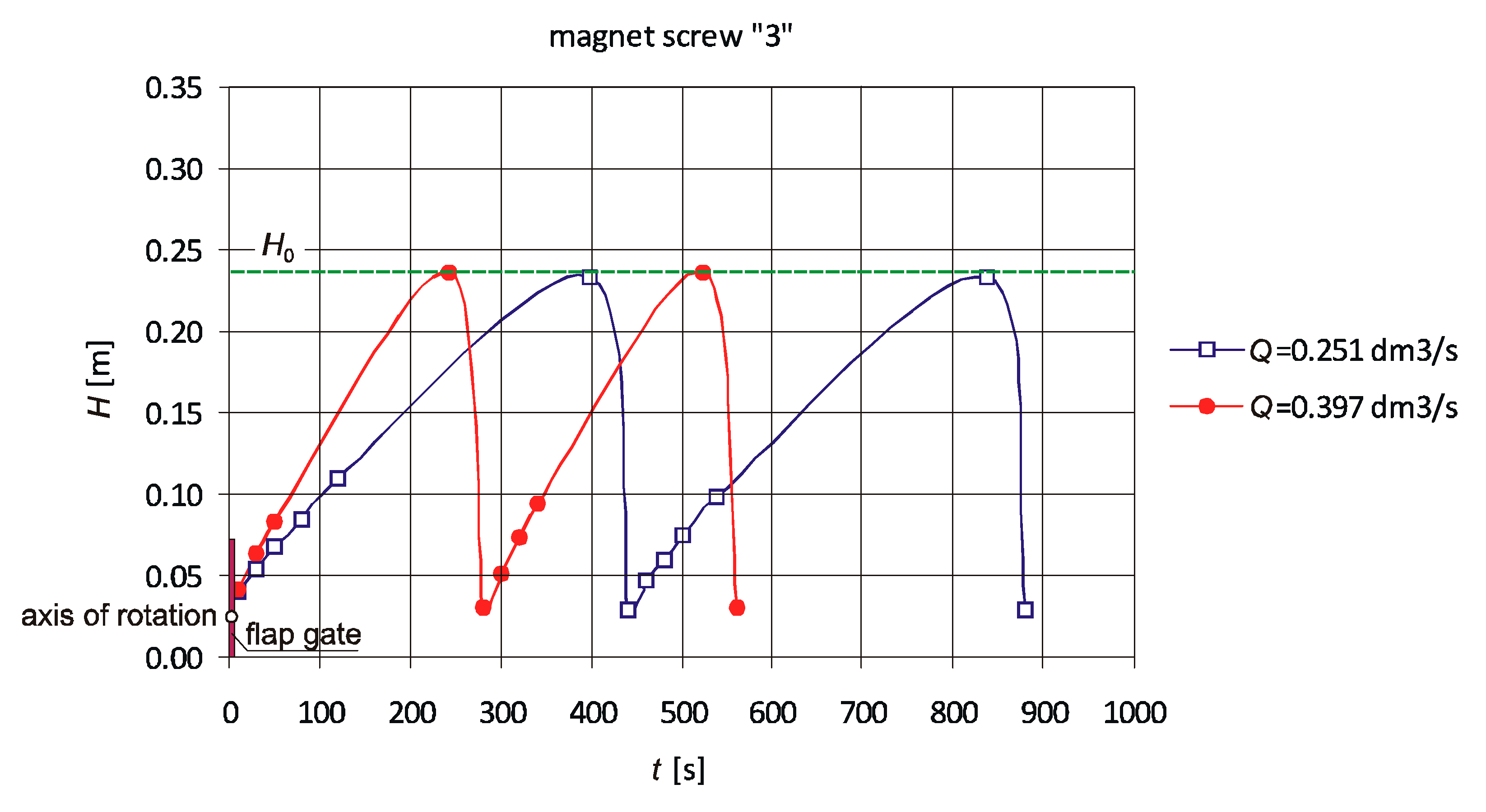
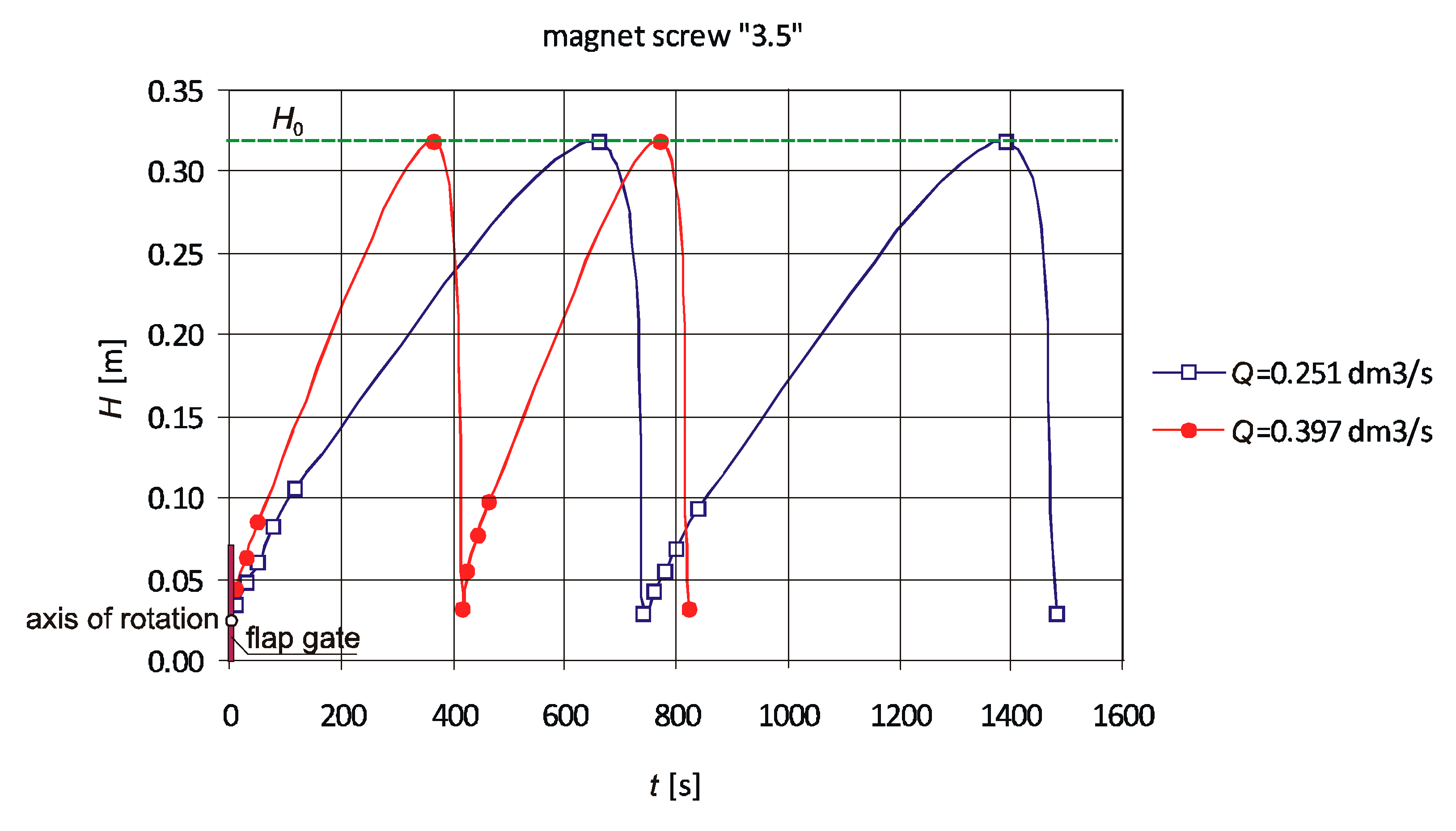
Figure 2). By changing the position of the magnet “0” to “3.5”, an increase in the upstream water level at which a gate opens can be achieved. The “0” position means that the magnet does not affect the closing moment.
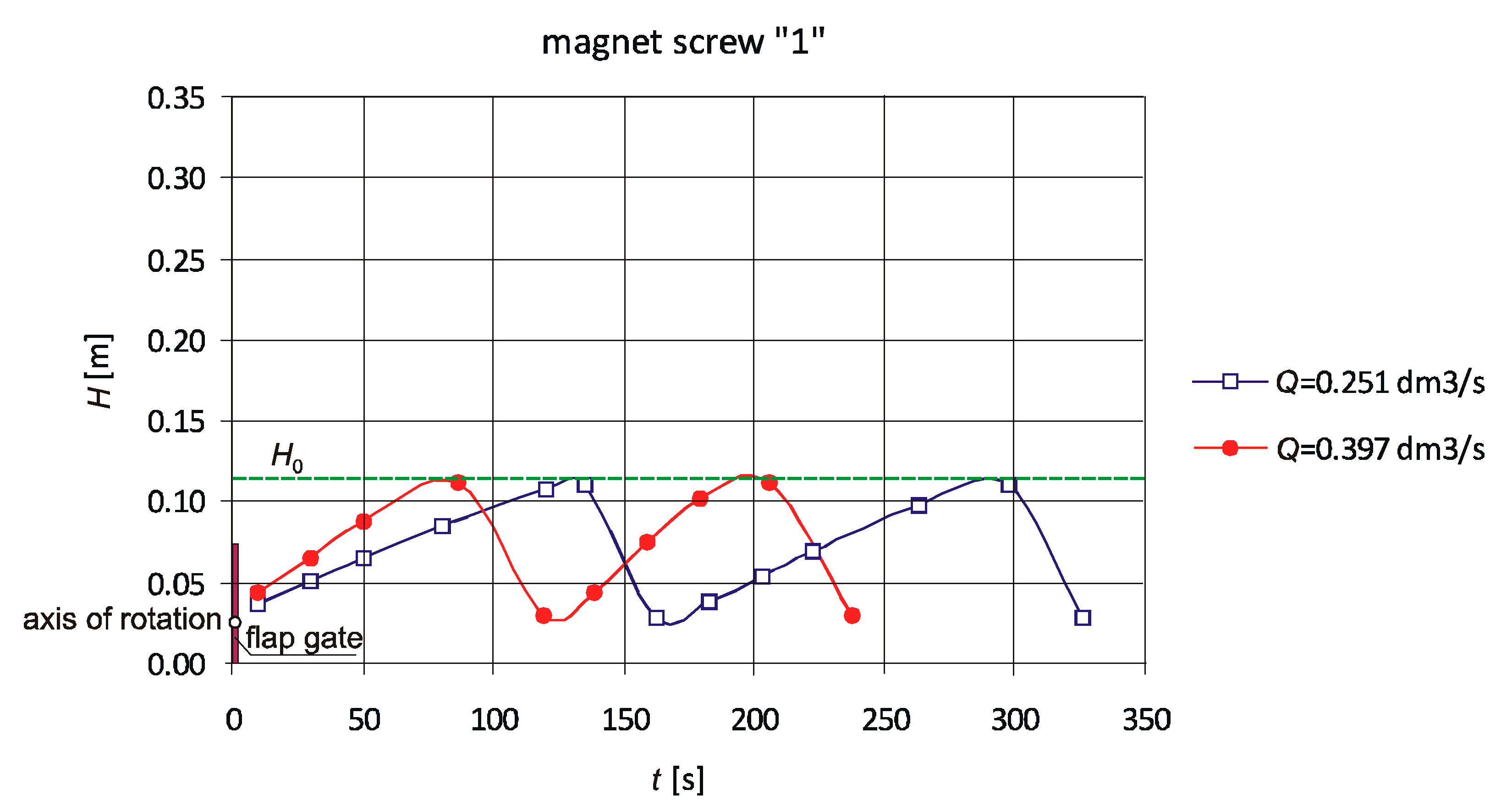
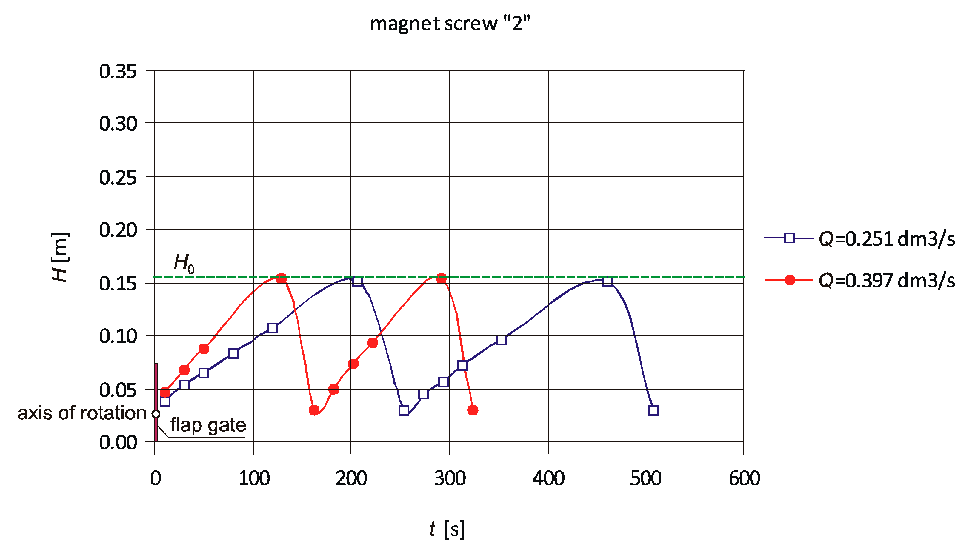
It should be noted that closing the flap gate does not stop the entire water flow. When the flap gate is closed, the volumetric flow rate of Qmin leaks at its contact with half-rings and through its fixation of an axis of rotation. At flow rates greater than Qmin, water is retained and the upstream water level increases to the designed level of H0. When the upstream water level exceeds H0, the flap gate opens automatically and water flows out through the pipe. Another parameter characterizing the device is the maximum flow rate of Qmax, at which the flap gate remains opened. When the water flow rate exceeds Qmax, the flap gate will not be able to close because the inflow to the device is greater than the outflow. The device operating range determines the flow variability of Qmin < Q < Qmax and the upstream water level of H0, beyond which the flap gate opens. After lowering of the upstream water level, the flap gate automatically closes due to its weight and the weight of the additional plates and the process of water retaining begins again. The aim of this work was to analyze the operating conditions of the designed device, experimentally determine the values Qmin and Qmax, and verify the theoretically derived formulas.
3. Analysis of Circular Flap Gate Working Conditions
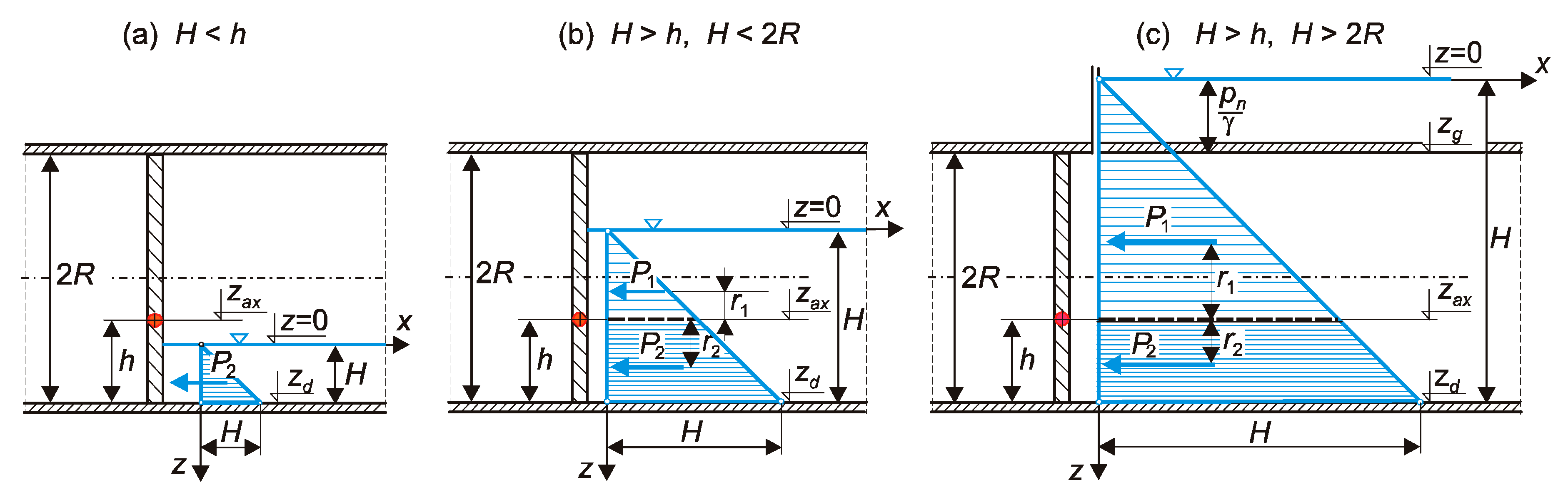
The conditions for opening the circular flap gate were analyzed for a case when the downstream water level is equal to 0. Due to the presence of the lower half-ring, the circular flap gate will not be able to open when the upstream water level
H is lower than the elevation of the axis of rotation above the lower edge of the flap
h (
H < h in
Figure 3). The flap gate opening is possible when the upstream water level is higher than the elevation of the flap gate axis of rotation above its bottom (
H > h in
Figure 3) and when the gate-opening moment caused by the hydrostatic force
P1 is higher than the gate-closing moment caused by the hydrostatic force
P2.
The necessary condition for the opening of the flap gate may be written as follows:
where
P1 is the hydrostatic force acting on a surface of the circular flap gate above its axis of rotation,
r1 is the moment arm of force
P1,
P2 is the hydrostatic force acting on a surface of the circular flap gate above its axis of rotation, and
r2 is a moment arm of force
P2.
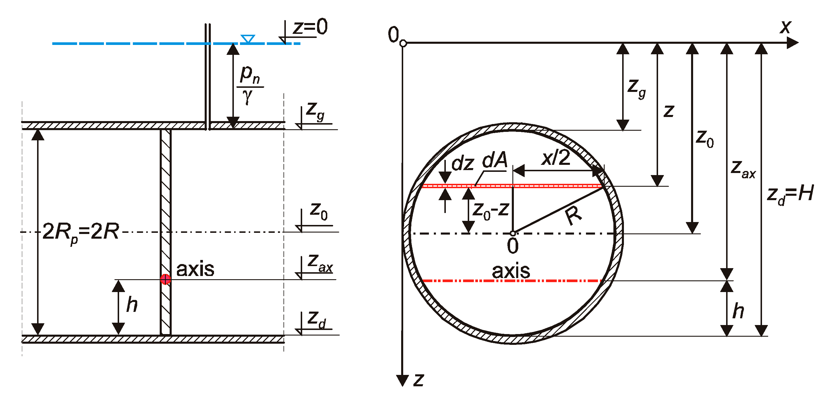
The differential hydrostatic force
dP acting on a differential surface of the flap
dA can be calculated on the basis of the fact that the pressure of a liquid with a specific weight of
γ at the depth of
z is equal to
p =
γz. The scheme of the circular flap gate in a pipe is shown in
Figure 4. It illustrates the notation used in the analysis.
The differential hydrostatic force
dP acting on a differential surface of the flap
dA is equal to
The differential surface area can be written as follows:
The length
x can be determined from the Pythagorean theorem:
The differential moment acting on a surface of
dA is equal to
On the surface of the circular flap gate above its axis of rotation, pressure exerts a gate-opening moment equal to
The closing moment acting on a surface of the circular flap gate below its axis of rotation can be written as follows:
From the boundary condition,
One can calculate the depth of the axis of rotation of the circular flap gate
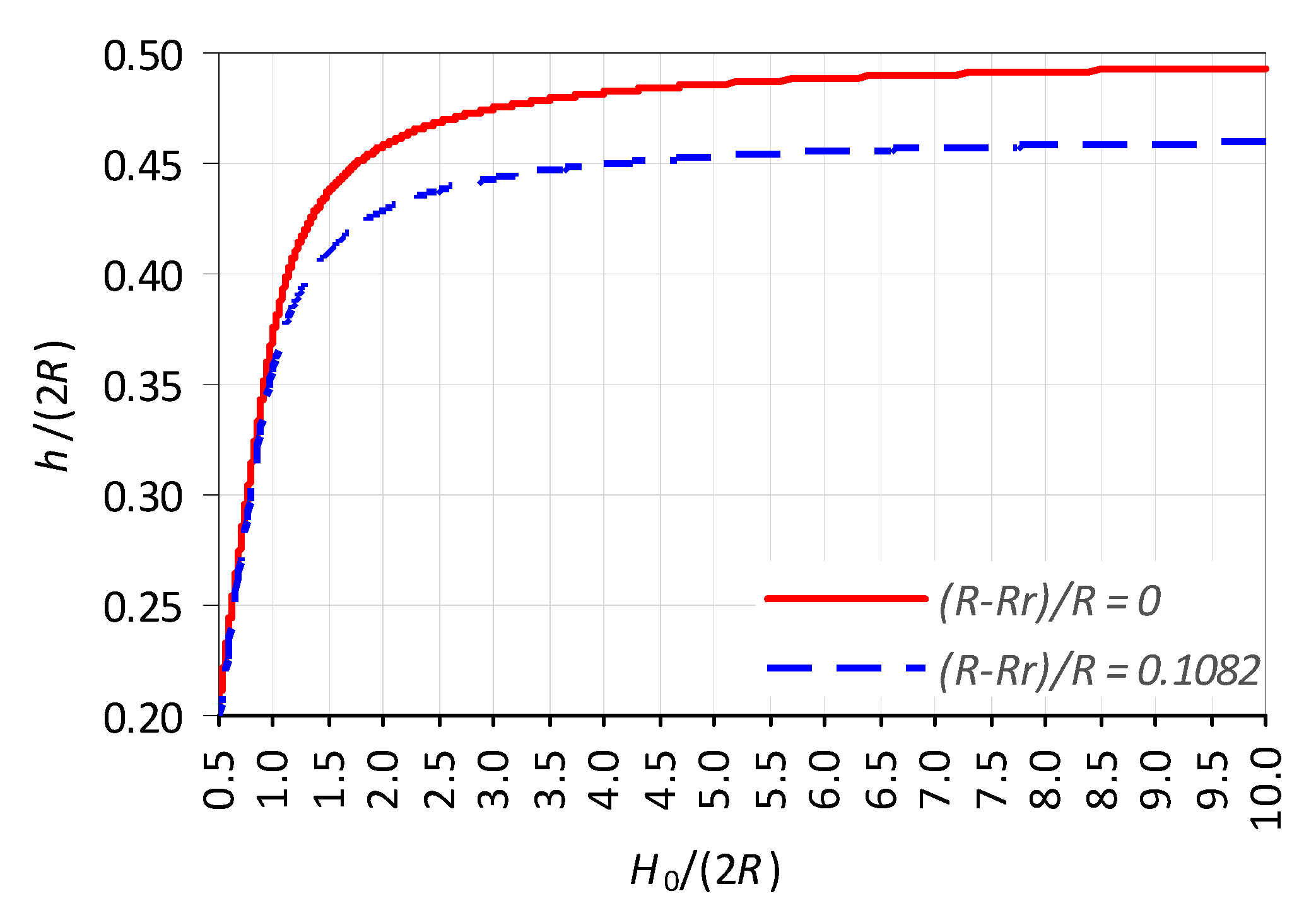
zax. Due to the complex form of the integrals in Equations (8) and (9), Simpson’s rule was used to calculate them. Firstly, after assuming the value of the upstream water level, the position of the circular flap gate axis of rotation was calculated. Exceeding the assumed upstream water level should cause a circular flap gate to open. The results of the calculations allowed us to establish a dimensionless relation between the elevation of the axis of rotation of the flap gate above its bottom
h and the upstream water depth at which the flap gate opens
H0 (
Figure 5). This relation can be used to determine, at the given upstream water depth
H0, the elevation of the axis of rotation of the flap gate above its bottom which causes it to open.
It should be noted that the upper half-ring affects the opening moment, as it reduces the surface area of the circular flap gate. The larger the radius of the upper half-ring, the lower the surface area on which hydrostatic force
P1 acts. Since the radius of the upper half-ring affects the opening moment, the relation between the elevation of the flap gate axis of rotation above its bottom
h and the upstream water depth at which a flap gate opens
H0 depends on the radius of the upper half-ring
Rr relative to the radius of the flap gate
R. The use of a half-ring with a radius of (
R −
Rr)/
R = 0.1082 for a 2
R diameter circular flap gate described later resulted in a decrease in elevation of the flap gate axis of rotation above its bottom
h and the upstream water depth at which a flap gate automatically opens
H0 (
Figure 5). The influence of the half-ring with the radius of
R−
Rr = 0.1082
R on the elevation of the flap gate axis of rotation above its bottom is shown in
Figure 5. For example, if the circular flap gate has no upper half-ring and were designed assuming that it opens at
H0/(2
R) = 1.0, then the elevation flap gate axis of rotation above its bottom should be equal to
h/(2
R) = 0.3750, so
h = 0.3750 (2
R). For comparison, assuming that the circular flap gate with the upper half-ring with the difference radius of
R−
Rr = 0.1082
R has to maintain the same upstream water depth of
H0/2
R = 1.0, the elevation flap gate axis of rotation above its bottom should be equal to
h/(2
R) = 0.3600, so
h = 0.3600 (2
R).
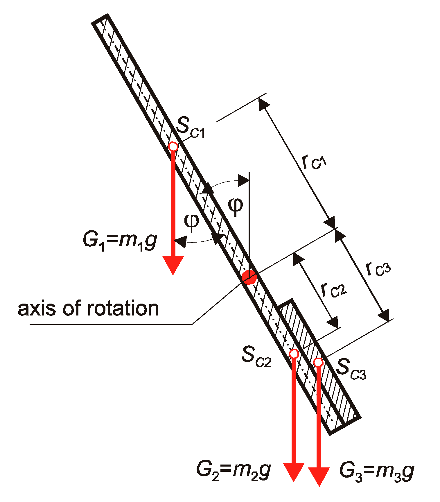
Since the axis of rotation of a circular flap gate is located below its center of mass, the gate will automatically close when (
Figure 6)
that is,
where
G1 and
G2 are the weights of the flap gate parts above and below the axis of rotation, g is the gravitational acceleration,
m1 and
m2 are the masses of the flap gate parts above and below the axis of rotation,
rC1 and
rC2 are the distances between the center of mass and the flap gate axis of rotation for flap gate parts above and below the axis of rotation, and φ is the angle between the gate and vertical axis.
The total mass of the circular flap gate is the sum of both parts:
In order for the flap gate to return to its original position and meet the condition (11), an additional weight
with a center of mass distant from the axis of rotation
rC3 must be attached to the surface below the axis of rotation (
Figure 6).
When designing the flow regulator, it was assumed that the additional mass would be attached in the form of metal plates with a height of
l cut from a circular plate with a diameter equal to the diameter of the flap gate 2
R. The required mass of the plates was calculated using the static equilibrium equation for the horizontal position of the gate (φ = 90°,
Figure 6):
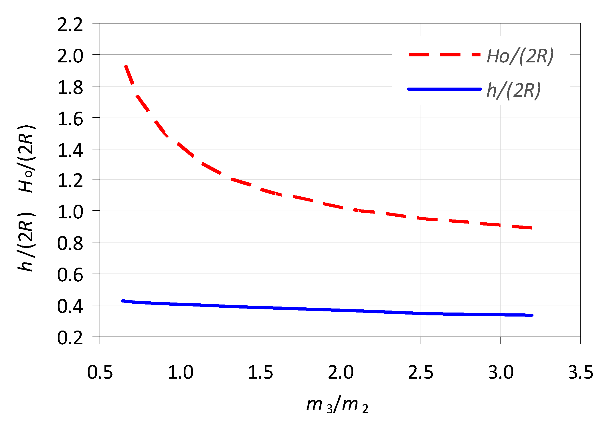
The values of the required mass of the additional plates
m3 in relation to the mass of the lower part of the flap gate
m2 are presented in
Figure 7 as a function of
h/(2
R) and
H0/(2
R). Due to the fact that in theoretical considerations friction was neglected, the required mass of the additional plate must be slightly greater than calculated. An increase of the additional
m3 mass increases the water level necessary to close the gate and, in this way, reduces the variability of the water levels upstream of the gate.
The relation presented in
Figure 7 shows that the required mass of additional plates for the automatic closing of the flap gate increases with the increase of the axis of rotation
h and the decrease of the upstream water level
H0, at which the flap gate opens. For
h/(2
R) = 0.4, the mass of the additional plates is equal to the mass of part of the flap gate below its axis of rotation (i.e.,
m2 =
m3). Lowering the position of the flap gate axis of rotation leads to a decrease in the upstream water level at which the flap gate opens
H0, but on the other hand, makes it necessary to increase the mass of the attached plates
m3 in order for the flap gate to close automatically. Maintaining the upstream water level by lowering and raising the position of the flap gate axis of rotation is not convenient. The increase of the upstream water level at a given position of the flap gate axis of rotation can be achieved by applying force on the upper edge of the flap gate that counteracts its opening. For this reason, a magnet with adjustable position was installed in the upper half-ring. The shorter the distance between the magnet and the flap gate, the larger the closing moment. Introduction of the magnet increases the gate-closing moment:
where
F is the magnet force, which maintains the gate in the closed position, and
is the distance from the flap gate axis of rotation to the force
F in the center of the magnet screw.
6. Conclusions
The operating conditions of the upstream water level circular flap control gate were analyzed. The dimensionless relations were given for determining the elevation of the circular flap gate axis of rotation as a function of upstream water depth at which the flap gate opens H0, the radius of the flap gate R, and the radius of the upper half-ring Rr. When the circular flap gate is closed, the volumetric flow rate of Qmin leaks at its contact with the half-rings and through its fixation of an axis of rotation. At flow rates greater than Qmin, water is retained and the upstream water depth increases to the designed depth of H0. When the upstream water depth exceeds H0, the circular flap gate automatically opens.
Another parameter characterizing the device is the maximum flow rate of Qmax at which the flap gate remains closed. When the water flow rate exceeds Qmax, the flap gate is unable to close because the inflow to the device is greater than the outflow.
The device operating range determines the flow variability of Qmin < Q < Qmax and the upstream water depth of H0, beyond which the flap gate opens. When the upstream water depth is lower than H0, the flap gate automatically closes due to its weight and the weight of the additional steel plates. By using a magnet-ended screw which “holds” the flap gate, smooth adjustment of the upstream water depth H0 can be achieved. The upstream water depth at which a circular flap gate opens was the same at different flow rates, which indicates that the flow rate has no effect on the H0. Changing the position of a magnet by bringing it closer to the flap causes an increase of the gate-closing moment, which results in an increase of the upstream water level at which the flap gate opens H0 and the minimum flow rate Qmin.


