Exergy Optimization of a Solar Collector in Flat Plate Shape Equipped with Elliptical Pipes Filled with Turbulent Nanofluid Flow: A Study for Thermal Management

 , ,
, ,
Abstract
:1. Introduction
2. Methodology
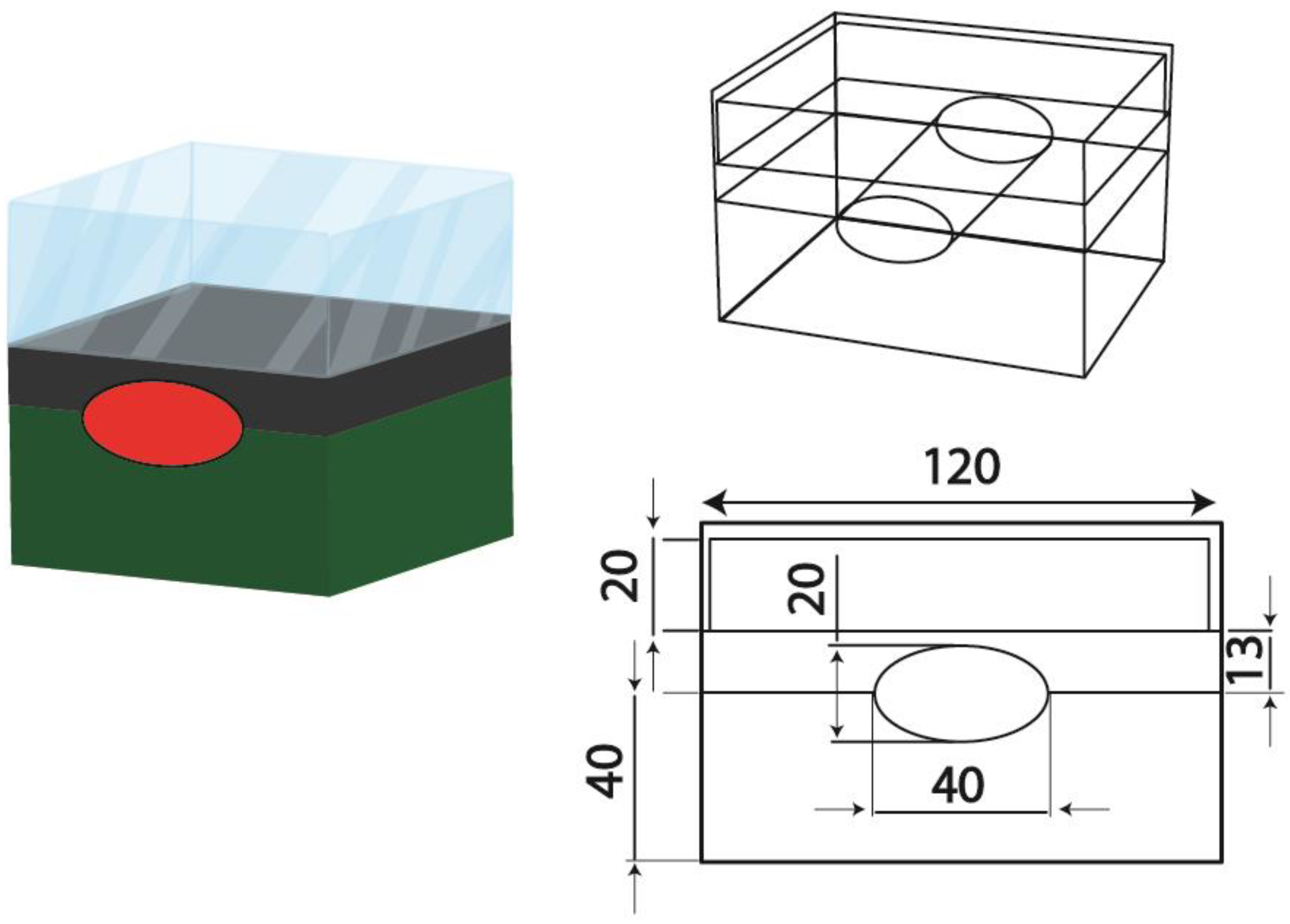
2.1. Physical Model
2.2. Conservation Equations
2.3. First Law Modeling
2.4. Second Law Modeling
2.5. Nanofluid
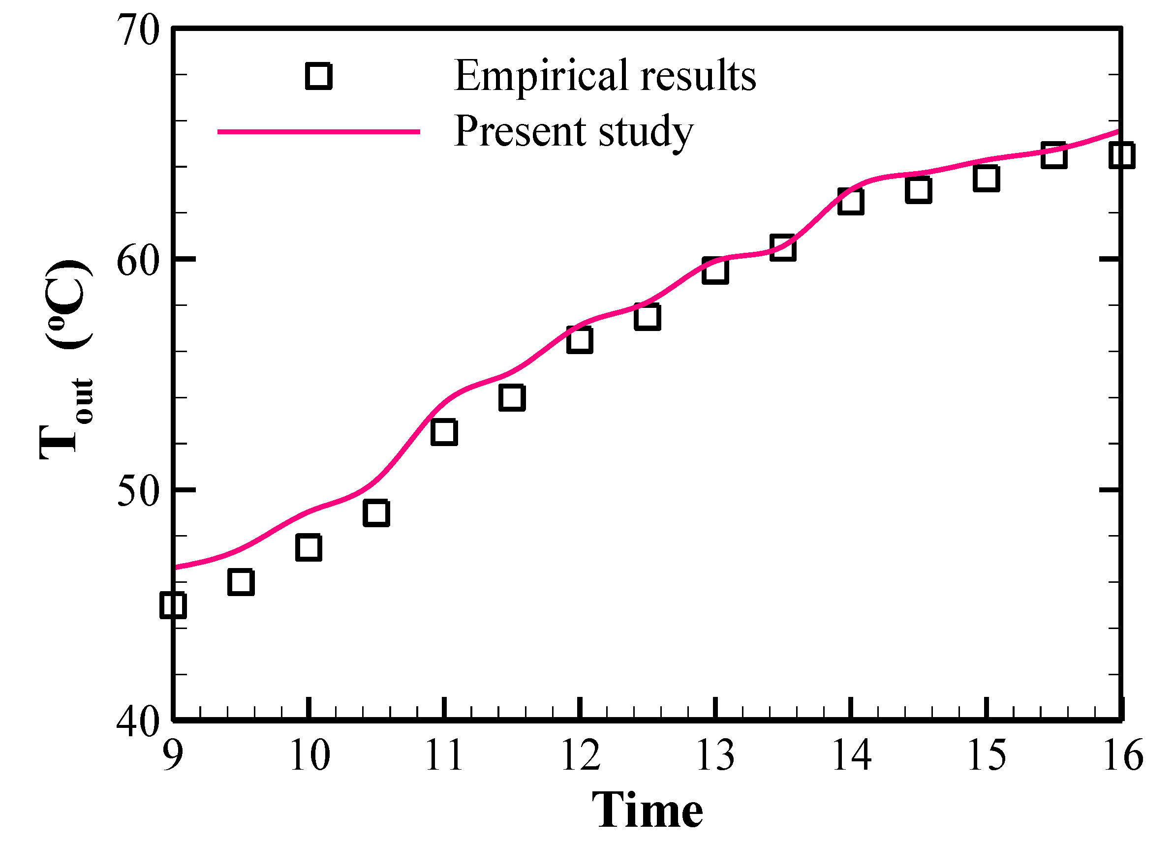
2.6. Verification and Grid Independence
3. Results
3.1. Energy and Exergy Analysis
3.2. Using a Nanofluid and Exergetic Optimization
4. Conclusions
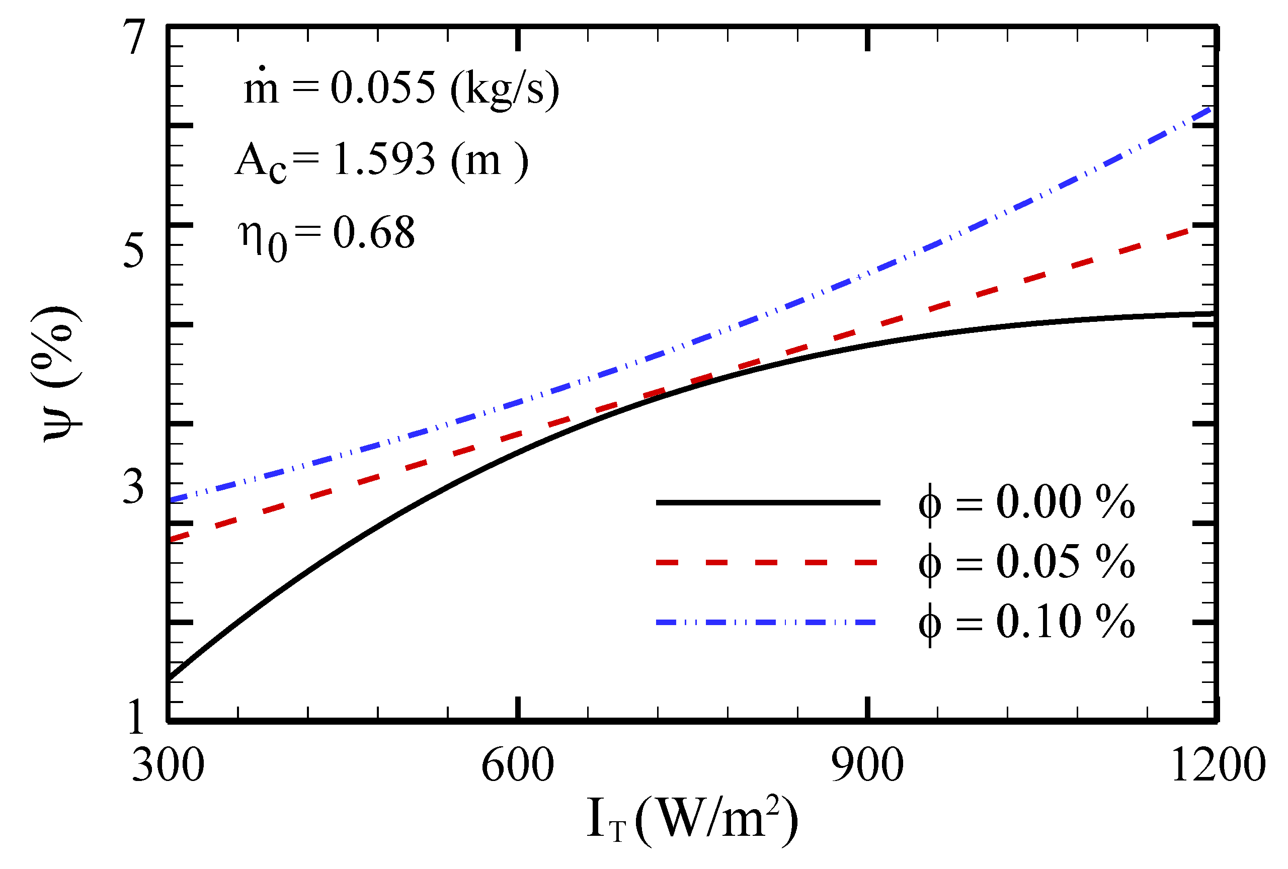
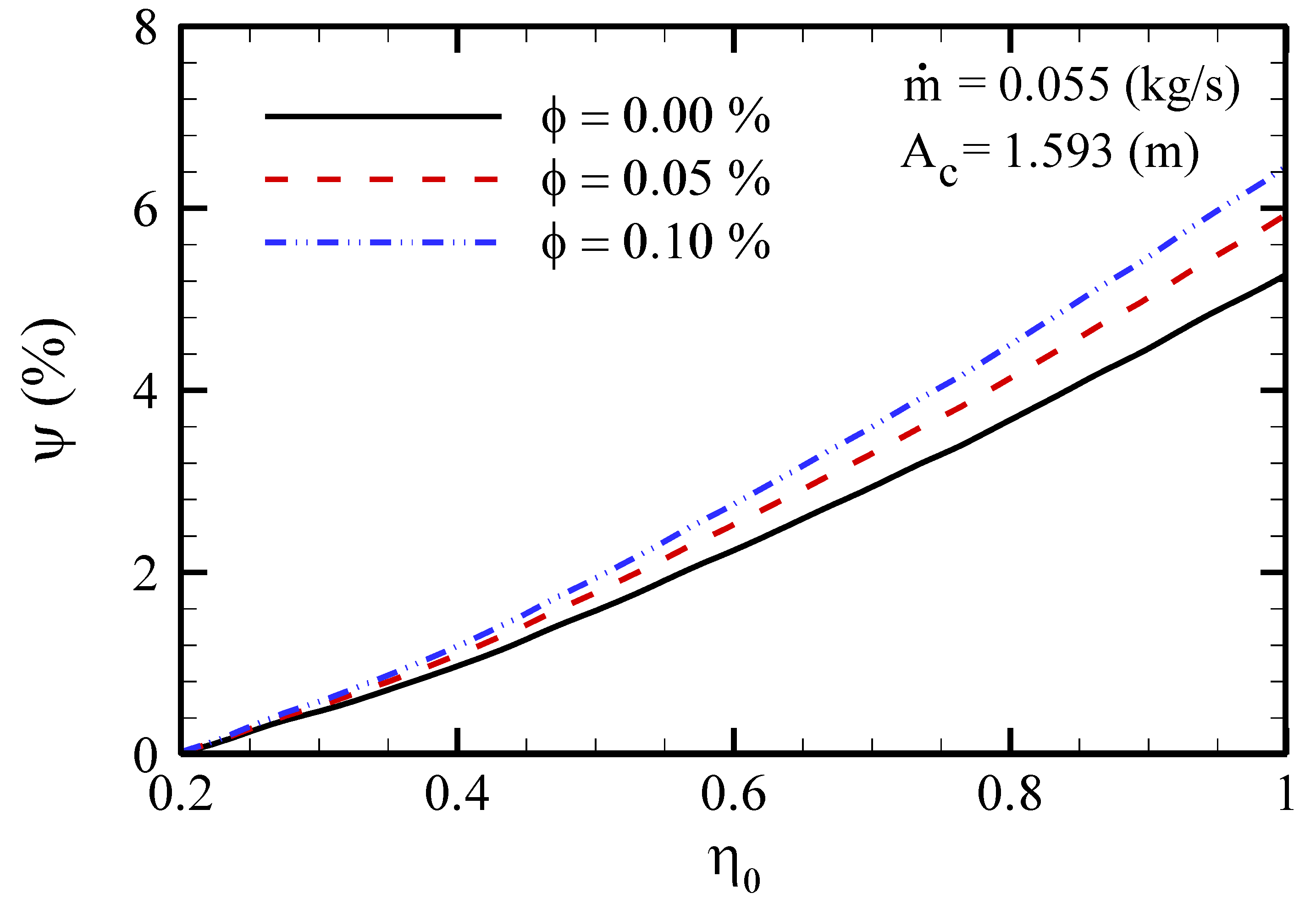
- An increase in solar radiation flux and optical efficiency entails an exergy efficiency increase for all conditions.
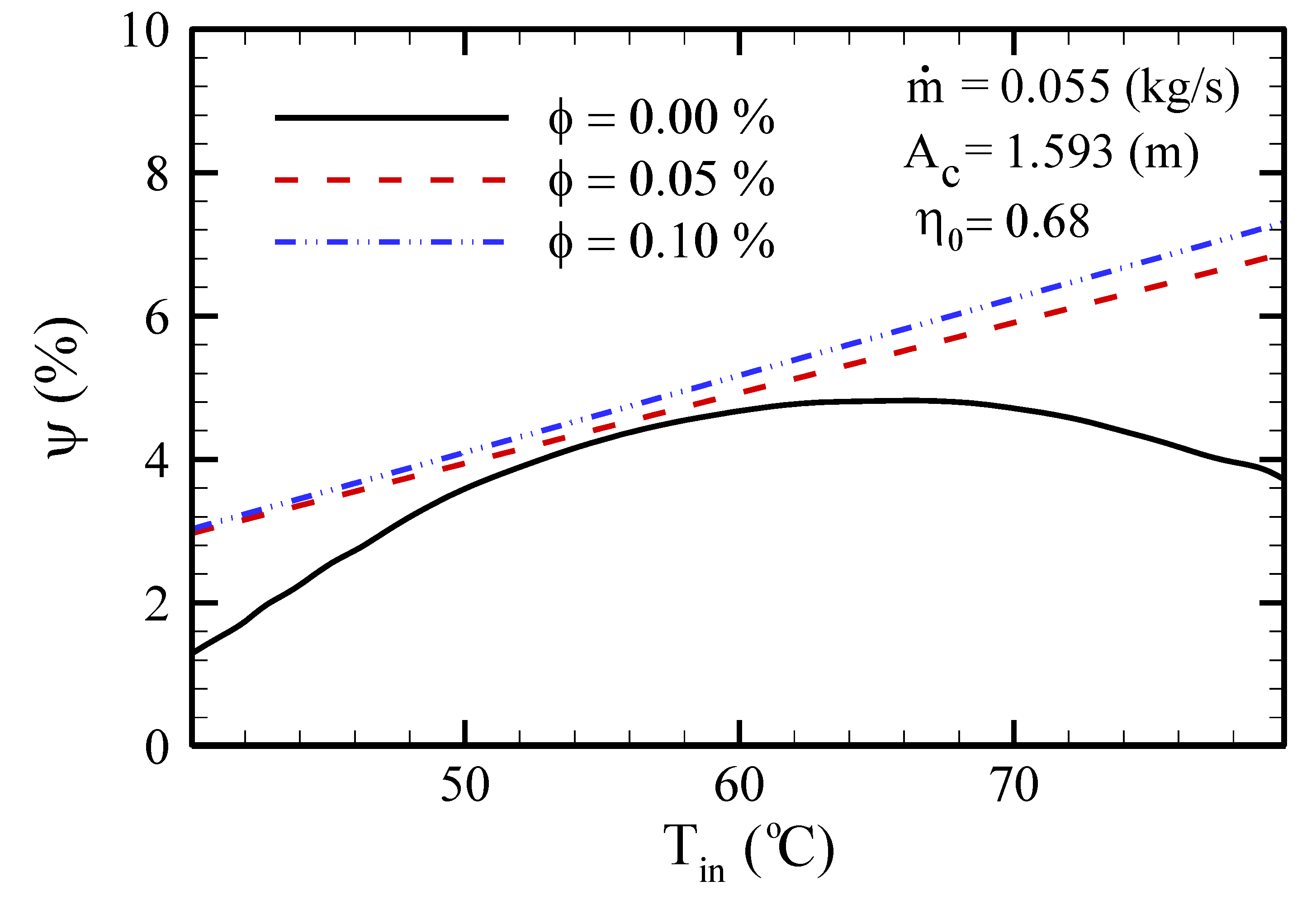
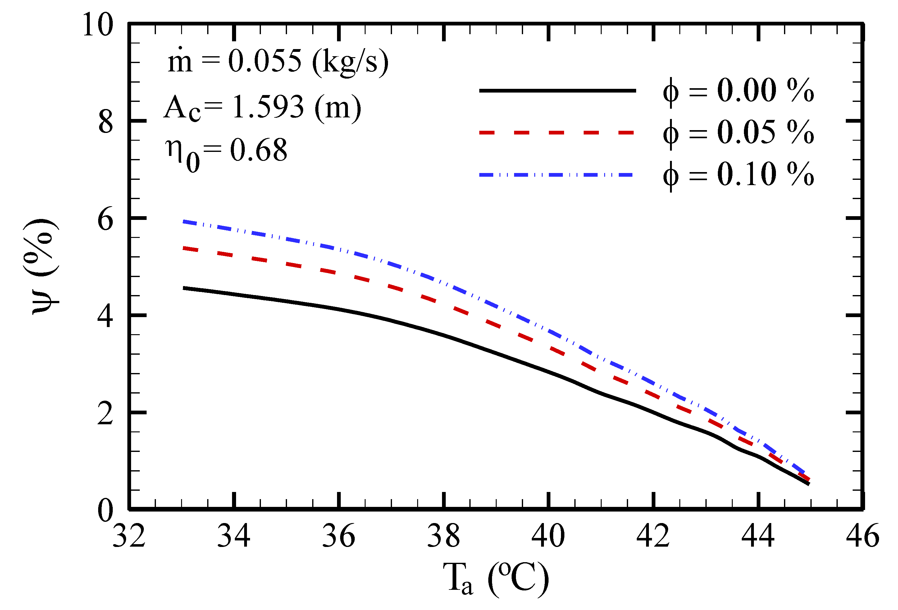
- The exergy efficacy diminishes as ambient temperature increases, but by increasing the FPSC inlet fluid temperature, the exergy efficacy rises to a certain temperature and then declines.
- With the use of an NF, the exergy efficiency always intensifies with a boost of inlet temperature.
- For higher mass flow rates of the base fluid, the efficiency first slightly declines and then remains unchanged. However, by using an NF, the maximum exergy efficiency occurs with the highest mass flow rate.
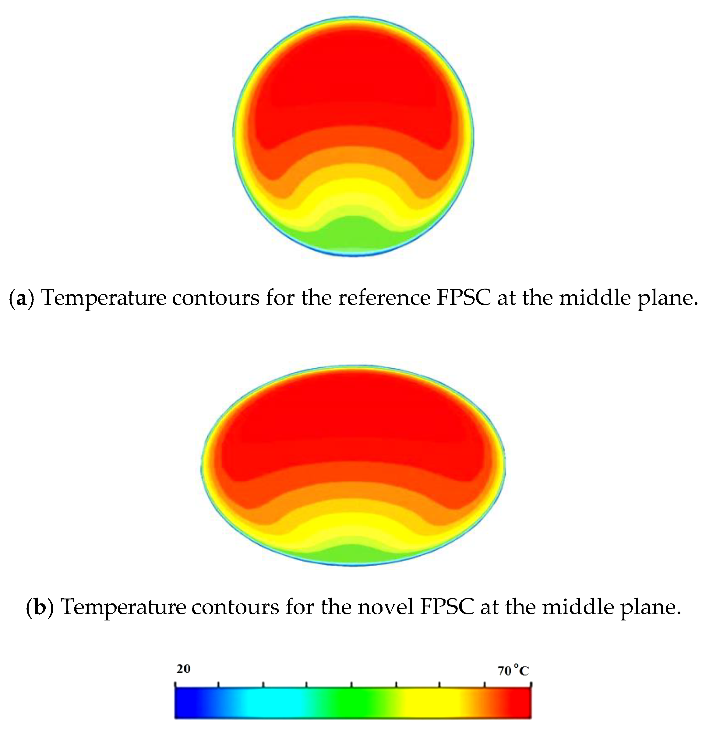
- Generally, using elliptical tubes and an NF enhances the exergy efficiency. In fact, while the trend of exergy efficiency variation with effective parameters is increasing, applying the elliptical tubes causes the efficiency to increase.
- The temperature increase entails an exergy efficiency increase to a certain point, and then this efficiency is diminished for higher values.
Author Contributions
Funding
Conflicts of Interest
Nomenclature
| A | area (m2) |
| cp | specific heat capacity (J kg−1 K−1) |
| Ė | rate of exergy (W) |
| hw | wind convection coefficient (W m−2) |
| I | solar intensity (W m−2) |
| Ib | beam radiation (W m−2) |
| Id | diffuse radiation (W m−2) |
| IT | daily average hourly (W m−2) |
| Iv | spectral radiation intensity (W m−2) |
| K | thermal conductivity (W m−1 K−1) |
| M | mass flow rate (kg s−1) |
| N | number of glass covers |
| P | pressure (Pa) |
| Ppump | pumping power (W) |
| S | section of solar radiation (W m−2) |
| T | temperature (K) |
| Ta | ambient temperature (K) |
| Tpm | mean temperature of absorber plate |
| U | velocity (m s−1) |
| u’ | fluctuated velocity (m s−1) |
| U | total loss coefficient (W m−2 K−1) |
| Vw | wind speed (m s−1) |
| Greek symbol | |
| α | absorption coefficient |
| ε | emission coefficient or dissipation |
| η | Efficiency |
| η0 | optical efficiency of collector |
| µ | viscosity (kg m−1 s−1) |
| μt | turbulent viscosity (kg m−1 s−1) |
| ρ | density (kg m−3) |
| σ | Stefan–Boltzmann constant (W m−2 K−4) |
| φ | latitude angle |
| Ω | hour angle |
| Subscripts | |
| a | ambient |
| c | collector |
| f | fluid |
| in | inlet |
| out | outlet |
| p | absorbent plate |
References
- Tian, M.-W.; Ebadi, A.G.; Jermsittiparsert, K.; Kadyrov, M.; Ponomarev, A.; Javanshir, N.; Nojavan, S. Risk-based stochastic scheduling of energy hub system in the presence of heating network and thermal energy management. Appl. Therm. Eng. 2019, 159, 113825. [Google Scholar] [CrossRef]
- Tian, M.-W.; Yuen, H.-C.; Yan, S.-R.; Huang, W.-L. The multiple selections of fostering applications of hydrogen energy by integrating economic and industrial evaluation of different regions. Int. J. Hydrog. Energy 2019, 44, 29390–29398. [Google Scholar] [CrossRef]
- Shenoy, D.V.; Shadloo, M.S.; Hadjadj, A.; Peixinho, J. Direct numerical simulations of laminar and transitional flows in diverging pipes. Int. J. Numer. Methods Heat Fluid Flow 2019, 30. [Google Scholar] [CrossRef]
- Tian, M.-W.; Yan, S.-R.; Tian, X.-X.; Kazemi, M.; Nojavan, S.; Jermsittiparsert, K. Risk-involved stochastic scheduling of plug-in electric vehicles aggregator in day-ahead and reserve markets using downside risk constraints method. Sustain. Cities Soc. 2020, 55, 102051. [Google Scholar] [CrossRef]
- Tian, M.-W.; Parikhani, T.; Jermsittiparsert, K.; Ashraf, M.A. Exergoeconomic optimization of a new double-flash geothermal-based combined cooling and power (CCP) system at two different cooling temperatures assisted by boosters. J. Clean. Prod. 2020, 261, 120921. [Google Scholar] [CrossRef]
- Tian, M.-W.; Wang, L.; Yan, S.-R.; Tian, X.-X.; Liu, Z.-Q.; Rodrigues, J.J.P.C. Research on Financial Technology Innovation and Application Based on 5G Network. IEEE Access 2019, 7. [Google Scholar] [CrossRef]
- Tian, M.; Yan, S.; Tian, X. Discrete approximate iterative method for fuzzy investment portfolio based on transaction cost threshold constraint. Open Phys. 2019, 17, 41–47. [Google Scholar] [CrossRef]
- Li, Z.; Shahsavar, A.; Niazi, K.; Al-Rashed, A.A.A.A.; Rostami, S. Numerical assessment on the hydrothermal behavior and irreversibility of MgO-Ag/water hybrid nanofluid flow through a sinusoidal hairpin heat-exchanger. Int. Commun. Heat Mass Transf. 2020, 115, 104628. [Google Scholar] [CrossRef]
- Pordanjani, A.H.; Aghakhani, S.; Afrand, M.; Mahmoudi, B.; Mahian, O.; Wongwises, S. An updated review on application of nanofluids in heat exchangers for saving energy. Energy Convers. Manag. 2019, 198, 111886. [Google Scholar] [CrossRef]
- Ghalandari, M.; Maleki, A.; Haghighi, A.; Shadloo, M.S.; Nazari, M.A.; Tlili, I. Applications of nanofluids containing carbon nanotubes in solar energy systems: A review. J. Mol. Liq. 2020, 313, 113476. [Google Scholar] [CrossRef]
- Shahsavar, A.; Khanmohammadi, S.; Afrand, M.; Shahsavar, A.; Rostami, S. On evaluation of magnetic field effect on the formation of nanoparticles clusters inside aqueous magnetite nanofluid: An experimental study and comprehensive modeling. J. Mol. Liq. 2020, 312, 113378. [Google Scholar] [CrossRef]
- Rostami, S.; Shahsavar, A.; Kefayati, G.R.; Goldanlou, S.A. Energy and Exergy Analysis of Using Turbulator in a Parabolic Trough Solar Collector Filled with Mesoporous Silica Modified with Copper Nanoparticles Hybrid Nanofluid. Energies 2020, 13, 2946. [Google Scholar] [CrossRef]
- Tian, Z.; Shahsavar, A.; Al-Rashed, A.A.A.A.; Rostami, S. Numerical simulation of nanofluid convective heat transfer in an oblique cavity with conductive edges equipped with a constant temperature heat source: Entropy production analysis. Comput. Math. Appl. 2019, in press. [Google Scholar] [CrossRef]
- Baniamerian, Z.; Mehdipour, R.; Kargar, F. A numerical investigation on aerodynamic coefficients of solar troughs considering terrain effects and vortex shedding. Int. J. Eng. Trans. C Asp. 2015, 28, 940–948. [Google Scholar]
- Ziapour, B.M.; Rahimi, F. Numerical study of natural convection heat transfer in a horizontal wavy absorber solar collector based on the second law analysis. Int. J. Eng. Trans. A Basics 2016, 29, 109–117. [Google Scholar]
- Ajay, K.; Kundan, L. Performance evaluation of nanofluid (Al2O3/H2O-C2H6O2) based parabolic solar collector using both experimental and CFD techniques. Int. J. Eng. Trans. A Basics 2016, 29, 572–580. [Google Scholar]
- Luminosu, I.; Fara, L. Determination of the optimal operation mode of a flat solar collector by exergetic analysis and numerical simulation. Energy 2005, 30, 731–747. [Google Scholar] [CrossRef]
- Shojaeizadeh, E.; Veysi, F. Development of a correlation for parameter controlling using exergy efficiency optimization of an Al2O3/water nanofluid based flat-plate solar collector. Appl. Therm. Eng. 2016, 98, 1116–1129. [Google Scholar] [CrossRef]
- Said, Z.; Saidur, R.; Rahim, N.A. Energy and exergy analysis of a flat plate solar collector using different sizes of aluminium oxide based nanofluid. J. Clean. Prod. 2016, 133, 518–530. [Google Scholar] [CrossRef]
- Hussein, A.K.; Kolsi, L.; Almeshaal, M.A.; Li, D.; Ali, H.M.; Ahmed, I.S. Mixed Convection in a Cubical Cavity with Active Lateral Walls and Filled with Hybrid Graphene–Platinum Nanofluid. J. Therm. Sci. Eng. Appl. 2019, 11, 041007. [Google Scholar] [CrossRef]
- RazaShah, T.; Ali, H.M. Applications of hybrid nanofluids in solar energy, practical limitations and challenges: A critical review. Sol. Energy 2019, 183, 173–203. [Google Scholar]
- UsmanSajid, M.; Ali, H.M. Recent advances in application of nanofluids in heat transfer devices: A critical review. Renew. Sustain. Energy Rev. 2019, 103, 556–592. [Google Scholar]
- Ali, H.M. Recent advancements in PV cooling and efficiency enhancement integrating phase change materials based systems—A comprehensive review. Sol. Energy 2020, 197, 163–198. [Google Scholar] [CrossRef]
- Shadloo, M.S. Numerical Simulation of Compressible Flows by Lattice Boltzmann Method. Numer. Heat Transf. Part A 2019, 75, 167–182. [Google Scholar] [CrossRef]
- Kassem, Y.; Çamur, H.; Aateg, R.A.F. Exploring Solar and Wind Energy as a Power Generation Source for Solving the Electricity Crisis in Libya. Energies 2020, 13, 3708. [Google Scholar] [CrossRef]
- Ahmed, S.; Muhammad Adil, H.M.; Ahmad, I.; Azeem, M.K.; e Huma, Z.; Abbas Khan, S. Supertwisting Sliding Mode Algorithm Based Nonlinear MPPT Control for a Solar PV System with Artificial Neural Networks Based Reference Generation. Energies 2020, 13, 3695. [Google Scholar] [CrossRef]
- Lee, Y.; Kim, B.; Hwang, H. Which Institutional Conditions Lead to a Successful Local Energy Transition? Applying Fuzzy-Set Qualitative Comparative Analysis to Solar PV Cases in South Korea. Energies 2020, 13, 3696. [Google Scholar] [CrossRef]
- Shaaban, M.F.; Alarif, A.; Mokhtar, M.; Tariq, U.; Osman, A.H.; Al-Ali, A.R. A New Data-Based Dust Estimation Unit for PV Panels. Energies 2020, 13, 3601. [Google Scholar] [CrossRef]
- Araújo, A. Thermo-Hydraulic Performance of Solar Air Collectors with Artificially Roughened Absorbers: A Comparative Review of Semi-Empirical Models. Energies 2020, 13, 3536. [Google Scholar] [CrossRef]
- Dijvejin, Z.A.; Ghaffarkhah, A.; Sadeghnejad, S.; Sefti, V. Effect of silica nanoparticle size on the mechanical strength and wellbore plugging performance of SPAM/chromium (III) acetate nanocomposite gels. Polym. J. 2019, 51, 693–707. [Google Scholar] [CrossRef]
- Ghaffarkhah, A.; Afrand, M.; Talebkeikhah, M.; Sehat, A.A.; Moraveji, M.K.; Talebkeikhah, F.; Arjmand, M. On evaluation of thermophysical properties of transformer oil-based nanofluids: A comprehensive modeling and experimental study. J. Mol. Liq. 2020, 300, 112249. [Google Scholar] [CrossRef]
- Parsa, S.M.; Davoud, J.Y.; Rahbar, A.; Majidniya, M.; Aberoumand, S.; Amidpour, Y.; Amidpour, M. Experimental assessment on passive solar distillation system on Mount Tochal at the height of 3964 m: Study at high altitude. Desalination 2019, 466, 77–88. [Google Scholar] [CrossRef]
- Parsa, S.M.; Davoud, J.Y.; Rahbar, A.; Majidniya, M.; Aberoumand, S.; Amidpour, Y.; Amidpour, M. Experimental investigation at a summit above 13,000 ft on active solar still water purification powered by photovoltaic: A comparative study. Desalination 2020, 476, 114146. [Google Scholar] [CrossRef]
- Parsa, S.M.; Rahbar, A.; Davoud, J.Y.; Koleini, M.H.; Afrand, M.; Amidpour, M. Energy-matrices, exergy, economic, environmental, exergoeconomic, enviroeconomic, and heat transfer (6E/HT) analysis of two passive/active solar still water desalination nearly 4000m: Altitude concept. J. Clean. Prod. 2020, 261, 121243. [Google Scholar] [CrossRef]
- Parsa, S.M.; Rahbar, A.; Koleini, M.H.; Aberoum, S.; Afrand, M.; Amidpour, M. Desalination, A renewable energy-driven thermoelectric-utilized solar still with external condenser loaded by silver/nanofluid for simultaneously water disinfection and desalination. Desalination 2020, 480, 114354. [Google Scholar] [CrossRef]
- Khorasanizadeh, H.; Aghaie, A. Determination of the monthly, seasonal, semi-yearly and yearly optimum tilted angles of flat plate solar collectors in Kashan. J. Energy Eng. Manag. 2014, 3, 38–49. [Google Scholar]
- Sadeghi, R.; Shadloo, M.S.; Hooman, K. Numerical Investigation of Natural Convection Film Boiling Around Elliptical Tubes. Numer. Heat Transf. Part A Appl. 2016, 70, 707–722. [Google Scholar] [CrossRef]
- Vanaki, S.M.; Mohammed, H.A.; Abdollahi, A.; Wahid, M.A. Effect of nanoparticle shapes on the heat transfer enhancement in a wavy channel with different phase shifts. J. Mol. Liq. 2014, 196, 32–42. [Google Scholar] [CrossRef]
- Gray, D.D.; Giorgini, A. The validity of the Boussinesq approximation for liquids and gases. Int. J. Heat Mass Transf. 1976, 19, 545–551. [Google Scholar] [CrossRef]
- ANSYS Fluent-Solver Theory Guide; Release 14.0; ANSYS Inc.: Canonsburg, PA, USA, 2011; pp. 351–353.
- Bejan, A. Convection Heat Transfer; Wiley-Interscience: Hoboken, NJ, USA, 1984. [Google Scholar]
- Duffie, J.A.; Beckman, W.A. Solar Engineering of Thermal Processes; John Wiley & Son: New York, NY, USA, 2006. [Google Scholar]
- Mechanical Agitator Power Requirements for Liquid. Available online: www.pdhonline.com/courses/k103/k103content.pdf (accessed on 12 August 2020).
- Suzuki, A. General theory of exergy balance analysis and application to solar collectors. Energy 1988, 13, 123–160. [Google Scholar] [CrossRef]
- Bejan, A.; Keary, D.W.; Kreith, F. Second law analysis and synthesis of solar collector systems. J. Sol. Energy Eng. 1981, 103, 23–28. [Google Scholar] [CrossRef]
- Bejan, A. Advanced Engineering Thermo-Dynamics; Wiley Inter science: New York, NY, USA, 1988. [Google Scholar]
- Dutta Gupta, K.K.; Saha, S. Energy analysis of solar thermal collectors. Renew. Energy Environ. 1990, 33, 283–287. [Google Scholar]
- Kahrobaian, A.; Malekmohammadi, H. Exergy optimization applied to linear parabolic solar collectors. J. Fac. Eng. 2008, 42, 131–144. [Google Scholar]
- Farahat, S.; Sarhaddi, F.; Ajam, H. Exergetic Optimization of Flat Plate Solar Collectors. Renew. Energy 2009, 34, 1169–1174. [Google Scholar] [CrossRef]
- Patel, H.E.; Anoop, K.B.; Sundararajan, T.; Das, S. Model for thermal conductivity of CNT-nanofluids. Bull. Mater. Sci. 2008, 31, 387–390. [Google Scholar] [CrossRef]


| Properties | Symbol | Quantity |
|---|---|---|
| Dimensions of FPSC | Lc × Wc (mm) | 200 × 92.5 |
| Slop of FPSC | β | 35° |
| Number of glass covers | N | 1 |
| Emissivity of glass covers | εg | 0.85 |
| Thickness of plate | δp (mm) | 0.1 |
| Emissivity of plate | εp | 0.9 |
| Conductivity of plate | kp (W·m−1·K−1) | 211 |
| Optical efficiency | η0 | 0.68 |
| Thickness of insulators | δi (mm) | 2.0 |
| Conductivity of insulators | ki (W·m−1·K−1) | 0.05 |
| Time | IT (W·m−2) | Ta (°C) | Tin (°C) | Vw (m·s−1) |
|---|---|---|---|---|
| 09:00 | 560 | 33 | 44.5 | 6 |
| 09:30 | 630 | 33 | 45 | 6 |
| 10:00 | 750 | 34 | 46 | 5 |
| 10:30 | 830 | 35 | 47 | 6 |
| 11:00 | 925 | 36 | 50 | 6 |
| 11:30 | 992 | 37 | 51 | 5 |
| 12:00 | 1006 | 38 | 53 | 5 |
| 12:30 | 1020 | 38.5 | 54 | 6 |
| 13:00 | 978 | 40.5 | 56 | 6 |
| 13:30 | 914 | 40.5 | 57 | 5 |
| 14:00 | 834 | 41 | 60 | 5 |
| 14:30 | 780 | 41 | 61 | 4 |
| 15:00 | 734 | 39.5 | 62 | 5 |
| 15:30 | 626 | 41 | 63 | 6 |
| 16:00 | 607 | 41 | 64 | 6 |
| Nodes | Tout (°C) | Error (%) |
|---|---|---|
| 3,243,983 | 66.6782 | 2.22 |
| 3,599,007 | 70.5134 | 1.05 |
| 3,728,623 | 70.7811 | 0.02 |
| 3,954,131 | 70.7834 | - |
| Time | UL (W/m2·K) | Tpm (°C) | Tout (°C) | η (%) | ψ (%) |
|---|---|---|---|---|---|
| 09:00 | 7.33 | 48.11 | 58.59 | 54.29 | 3.34 |
| 09:30 | 7.37 | 49.06 | 59.61 | 57.48 | 3.53 |
| 10:00 | 7.32 | 51.32 | 61.04 | 57.78 | 3.95 |
| 10:30 | 7.49 | 52.41 | 62.61 | 64.40 | 4.21 |
| 11:00 | 7.56 | 54.25 | 65.82 | 63.00 | 4.35 |
| 11:30 | 7.52 | 57.07 | 67.07 | 63.68 | 4.58 |
| 12:00 | 7.56 | 58.42 | 69.23 | 61.91 | 4.60 |
| 12:30 | 7.77 | 59.31 | 70.26 | 61.54 | 4.55 |
| 13:00 | 7.76 | 60.46 | 72.04 | 61.48 | 4.54 |
| 13:30 | 7.40 | 60.57 | 72.61 | 60.16 | 4.68 |
| 14:00 | 7.73 | 63.22 | 75.13 | 58.64 | 4.67 |
| 14:30 | 7.55 | 63.47 | 75.77 | 57.57 | 4.56 |
| 15:00 | 7.77 | 63.89 | 76.41 | 56.91 | 4.41 |
| 15:30 | 7.94 | 64.09 | 76.91 | 56.28 | 4.21 |
| 16:00 | 7.97 | 65.11 | 77.82 | 55.62 | 4.15 |
| Time | UL (W/m2·K) | Tpm (°C) | Tout (°C) | η (%) | ψ (%) |
|---|---|---|---|---|---|
| 09:00 | 7.15 | 47.08 | 53.23 | 64.04 | 6.34 |
| 09:30 | 7.21 | 48.02 | 54.24 | 67.83 | 6.88 |
| 10:00 | 7.08 | 50.27 | 55.51 | 68.18 | 7.77 |
| 10:30 | 7.25 | 51.33 | 57.49 | 75.98 | 8.34 |
| 11:00 | 7.32 | 53.21 | 59.61 | 74.34 | 8.71 |
| 11:30 | 7.35 | 56.00 | 62.29 | 76.44 | 9.21 |
| 12:00 | 7.34 | 57.32 | 63.71 | 74.28 | 9.98 |
| 12:30 | 7.51 | 58.14 | 64.40 | 73.81 | 8.75 |
| 13:00 | 7.56 | 59.32 | 65.87 | 73.78 | 8.62 |
| 13:30 | 7.30 | 59.52 | 66.01 | 72.78 | 8.93 |
| 14:00 | 7.60 | 62.13 | 68.82 | 69.14 | 8.87 |
| 14:30 | 7.38 | 62.42 | 68.99 | 69.08 | 8.81 |
| 15:00 | 7.59 | 62.64 | 69.11 | 66.58 | 8.51 |
| 15:30 | 7.67 | 63.01 | 69.25 | 65.84 | 8.01 |
| 16:00 | 7.69 | 64.12 | 69.34 | 65.63 | 7.88 |
© 2020 by the authors. Licensee MDPI, Basel, Switzerland. This article is an open access article distributed under the terms and conditions of the Creative Commons Attribution (CC BY) license (http://creativecommons.org/licenses/by/4.0/).
Share and Cite
Rostami, S.; Sepehrirad, M.; Dezfulizadeh, A.; Hussein, A.K.; Shahsavar Goldanlou, A.; Shadloo, M.S. Exergy Optimization of a Solar Collector in Flat Plate Shape Equipped with Elliptical Pipes Filled with Turbulent Nanofluid Flow: A Study for Thermal Management. Water 2020, 12, 2294. https://doi.org/10.3390/w12082294
Rostami S, Sepehrirad M, Dezfulizadeh A, Hussein AK, Shahsavar Goldanlou A, Shadloo MS. Exergy Optimization of a Solar Collector in Flat Plate Shape Equipped with Elliptical Pipes Filled with Turbulent Nanofluid Flow: A Study for Thermal Management. Water. 2020; 12(8):2294. https://doi.org/10.3390/w12082294
Chicago/Turabian StyleRostami, Sara, Mohammad Sepehrirad, Amin Dezfulizadeh, Ahmed Kadhim Hussein, Aysan Shahsavar Goldanlou, and Mostafa Safdari Shadloo. 2020. "Exergy Optimization of a Solar Collector in Flat Plate Shape Equipped with Elliptical Pipes Filled with Turbulent Nanofluid Flow: A Study for Thermal Management" Water 12, no. 8: 2294. https://doi.org/10.3390/w12082294